This tracer program is free and works pretty good, link: FPGraphTracer : fprawn labs.
Below see some example how to edit in MS paintbrush before tracing so that FPGraphTracer outputs clean result. For first example (stereophile speaker review) task is to get blue curve clean without distortions from red curve and grid lines and for second example (B & K curve) task is to get get same color grid lines not to distort. Tip FPGraphTracer doesn't care if it can see grid lines or not as user we just need a little grid line to be back to tell program where they sits and the value in number there.
This was the tool I needed. I just finished my crossover now.
Putting a RC circuit (zobel) is creating a flat filter response graph. Example, woofer has a 1st order (just an inductor) crossover. Putting the RC after the inductor is not showing the flat impedence response but is showing the filtered response. Putting the RC circuit before the inductor is showing the filer response but not the flat impedance. In this example R=8 and C=27 but any typical RC (zobel) should give a similar response. I'm must wondering if this is normal and as for the RC circuit it should come after the inductor regardless of the simulation.
See the two screenshots - both made today under the following conditions:
- all equipment and speaker under test static
- air temp within +/- 2C
- humidity stable
- mic is a calibrated Beyerdynamic MM1 (even if it comes calibrated out of the factory)
- mic amp is a StageLine MPA102 suggested by the lab that did the calibration
Xsim produces (evident) a massive spike in the input response where the actual measurement does not exhibit such pattern. I very much like its interface but this glitch and the lack of target responses still forces me to use other softare. Otherwise its pretty nice. Would be interested to hear comments on what could cause this erratic behaviour.
Attachments

Hi Mario Pankov,
Normal XSim predictions is in sync with real world so something most be filled or executed in wrong way.
Have two comments to look for mistakes, first is can see some excess dots on wires in schematic window and these points to maybe some wires is a short under some components and to seek for these hidden wires lift every component and drivers to one side to look for if a short is underneath, second fault to look for is because we can see both drivers have some delay added seen by the "m" symbol and think that is strange because normal one is reference and then the other is either advanced or delayed relative to reference, so look for any weird delay settings that makes the two drivers cancel.
Regarding target curves you have possibility to read in one more curve via "Curves" menu "Get file" and besides that you can open up XSim multiple times with same basic file and then add a different target curve to each of the multiple.
Target curves you can create in free Rephase as wav impulse response file (use same samplerate as measurement chain) and then into free REW offset SPL to whatever target and export as frd file for use in XSim. Below is example based your schematic with a green target curve example that is LR 2nd order at 2kHz, frd files for both drivers was also created in Rephase over to REW then over to XSim drivers S1/S2 and for info woofer was BW2 20Hz-3kHz and tweeter was BW2 800Hz-22kHz and then we see for rest what your component values correct to those band passes.
Attachments

Last edited:
Thanks for the curves suggestion, will try it.
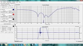
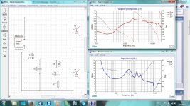
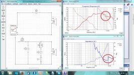
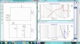
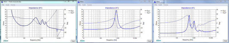
No, the extra dots do not correspond to wires that might be invisible. No delay on both. Have a look below. First one is directly connected .FRD. It looks normal as the recorded frequency response. Now, I`d add a capacitor - 10uF - immediately there is this erratic response at 8Khz. Photo 3 has the cap reduced to 3uF - look at the effect. I had abandoned XSim as I was using PCD and it worked fine but recently switched to LibreOffice whose Macros appear coded differently and it can`t launch the PCD. So went back to XSim but something is wrong here and I wonder what.
No, the extra dots do not correspond to wires that might be invisible. No delay on both. Have a look below. First one is directly connected .FRD. It looks normal as the recorded frequency response. Now, I`d add a capacitor - 10uF - immediately there is this erratic response at 8Khz. Photo 3 has the cap reduced to 3uF - look at the effect. I had abandoned XSim as I was using PCD and it worked fine but recently switched to LibreOffice whose Macros appear coded differently and it can`t launch the PCD. So went back to XSim but something is wrong here and I wonder what.
Attachments
Can see it looks weird and don't think its because you don't have any ground symbol in schematic window, but suggest try remove zma file for S1 and keep its frd file and see what happens then when adding a capacitor, say this because glitch at 8kHz in impedance plot in first attachment is not normal looking and its impedance phase shift is enormous.
Well spotted, once the impedance is removed, the frequency response becomes as measured. Is it possible the phase in the .ZMA file to be in conflict with the phase in the .FRD?
Great it worked, about that zma file think its flawed from beginning because look at its other places of variances in few ohms and nowhere its causing phase shift as enormous as that little resistive glitch at around 8kHz, so try probe driver once again for a better and true zma curve, maybe close all other programs when measuring for impedance so as computer have most possible resources to get glitch free curve.
Just look at the impedance for that driver (you can select S1 in the Curves menu of the impedance graph). See if there is anything odd with it. You can also look at the .ZMA file with a text editor to see what looks wacky there -- there won't be any abrupt impedance magnitude changes in a real driver and impedance angles more than 90 degrees or less than -90 degrees are impossible.
Impedance will not have ANY effect if you connect just the driver to the ideal "Power amp", it can drive anything!
Impedance will not have ANY effect if you connect just the driver to the ideal "Power amp", it can drive anything!
Hi Bill,
Thanks for dropping by. I did explore what could be wrong and noticed the impedance in the ZMA measurement (exported in column data) starts to decrease after 8Khz with a 90 degree phase change. This is not possible so today dismantled my resistor box to see whats wrong in it and I think I found the reason but am to tired to work on it today.
Thanks for dropping by. I did explore what could be wrong and noticed the impedance in the ZMA measurement (exported in column data) starts to decrease after 8Khz with a 90 degree phase change. This is not possible so today dismantled my resistor box to see whats wrong in it and I think I found the reason but am to tired to work on it today.
.....today dismantled my resistor box to see whats wrong in it and I think I found the reason but am to tired to work on it today.
Don't know what jig and software are used but it looks missing DC component and above resonance a raising impedance as frq goes up, if it can help here is camparison to your curve how DATS sweep looks for two nominal 8 ohm units one is Monarcor DT-254 tweeter and one is JBL 2426H in 2370A horn.
Attachments
There was a broken solder joint inside the test box, I use these often for car installs and here you go. All fine now (even changed the resistor to a non-indutive type haha).
Dear Mr. Waslo,
Xsim has taught me more about crossovers than I ever thought I would ever KNOW!
Easy to use - it is simply one of the greatest gifts I have ever received.
I do have a question to ask you - watch out it might turn into two!
What do you think of using a paralleled capacitor across the driver as a low pass filter? I have tried this and it seems to sound good. Doesn't look like it is doing anything funny on Xsim but would still like your opinion. You are one of the AUDIO gods having been mentioned in SOUND PRACTICES! You knew more by the time of your thirties than I will ever know!
I am using this to better integrate a JBL 2441 with a FOSTEX T500. The FOSTEX sure sounds better without interference from the 2441. I was using a series choke, before, and this sounds better (so far). Aesthetically I like the idea of no series components.
So here is the second one - I no longer have a series resistor in the path to same JBL 2441 I am using a very low value resistor in parallel with the driver.
Other than presenting a low impedance to the amplifier is there anything else WRONG about doing this? it seems to sound better.
Before I was using the series resistor with a parallel cap to get a rise in the response which I thought I needed. I did not so no need for the resistance. In addition I wanted to use as small a choke as I could for the high pass filter and get high damping for a low Q.
Your opinion would be greatly appreciated.
Just thought of the third one.
My amplifier has a specified output impedance of 4 ohms.
Should I make use of this within Xsim? Is it as simple as placing a 4 ohms resistor on the output of MAGIC XSim amplifier or is that ridiculous?
I am thinking I should make an impedance plot of the 2441 using this amplifier instead of the headphone amp within the FOCUSRITE box.
I promise, this should do it.
Thanks and take care,
Is it a solid state amplifier or valve ?Just thought of the third one.
My amplifier has a specified output impedance of 4 ohms.
If it's solid state its extremely unlikely that it has an output impedance above about 0.2 ohms...
In which case you may be misreading the spec which is probably saying it can drive loads down to 4 ohms, which would be typical of most solid state amplifiers, not that it has an output impedance of 4 ohms.
If your amplifier really does have an equivalent series output impedance of 4 ohms - which is only likely with a valve amplifier, then yes, just place a 4 ohm resistor in series with the output of the "amplifier" in the Sim.Should I make use of this within Xsim? Is it as simple as placing a 4 ohms resistor on the output of MAGIC XSim amplifier or is that ridiculous?
Yes, it is solid state but it is the First Watt SIT 1 amplifier and it is indeed four ohms!
Thanks for the assurance.
Thanks for the assurance.
Hi Rick,
Sorry for late response, we were out of town (to RMAF, then a week in the Rocky Mountains themselves) and I just saw your posts.
Simon's right about *most* solid states, but when you get to exotica like First Watt, general rules go by the wayside. If the output impedance is 4 ohms, and is constant through the audio band, then, yeah, you want to include a 4 ohm resistor on the amp output in your modeling. A problem would be if it isn't constant (resistive) throughout the audio band, then things get more complicated pretty fast.
Do you have a setup for measuring impedance (like a DATs unit or the like)? If so, you might want to actually measure your amp's output impedance. One way is to use the DATs (best to do it with a battery-isolated laptop so no funny ground connections get into it in case the amp topology is odd) and put a ~4 ohm resistor in series with the amp and measure those in combo. Then measure the amp's output impedance and just subtract 4 ohms resistive from whatever you measure. Better ways are to measure the amp's response with no load and then with a lowish impedance load, then back-calculate the impedance, but that can get to be a handful of math and requires less common measurement gear. If you do get a measure of impedance and it isn't flat, then you'd have to come up with a network that gives the same impedance.... fun.
Seeing as you have a 4 ohm (or so) resistor effectively inline with your amp and speaker cable, a capacitor across the tweeter is probably safe with it, but I'd be very concerned doing that should you ever try to drive that speaker with a more usual feedback amplifier -- stiff capacitive loads have a tendency to make some amplifiers burst into flames, not a good thing. A paralleled capacitor isn't a lowpass filter unless it is fed via a resistor (actual or via an amp's high output impedance). Without one, it can be become a torture load for a low output impedance amp at high frequencies, or an oscillation generator for amps with feedback on their outputs.
Put a 4 ohm resistor at the amp in your xsim model and see what it is all doing. If I were you, I'd try to get a design that works well with that amp as well as with a more typical amp. But that would mean you'd have to compensate the circuit so the speaker has a basically flat impedance, which takes more parts and likely means losing sensitivity/efficiency.*
*BTW, you might find that with a speaker with flat impedance, the amp could lose some of its "sounds different" magic, if that magic was from frequency response wiggles caused by load impedance variations!
Last edited:
*BTW, you might find that with a speaker with flat impedance, the amp could lose some of its "sounds different" magic, if that magic was from frequency response wiggles caused by load impedance variations!
When that happens the suspect is more the design of the amplifier. Different sounds due to load variations are not the mark of a well thought out amplifier design.
Those output versus load variations are more common than we are lead to believe.
Some amplifier reviewers still use a capacitive load test and an inductive load test to run the amplifier under review.
Thanks for your counsel, Mr. Waslo and no need for apologies!
I worried you had lost interest in this great thing. So many of us could benefit greatly from taking a few measurements and seeing what happens. Maybe I should not admit it but I have spent hours trying different combinations and arrangements. Almost hypnotic! Even better than FREECELL!!!
I have found from going back and forth between trying an arrangement on the speaker and then measuring and comparing to the Xsim prediction that I get a response closer to the predicted one when I put the four ohms resistor in the circuit. When I measure the impedance of the whole crossover/driver it does not reflect that 4 ohms, needless to say, so adding the resistor is good for response but not for impedance prediction.
I was in pursuit of no series resistors or chokes in the network and have had to give up on this. Compromise is always in the mix. I get an impedance curve that I know has to make the amplifier happier and a response that measures and sounds better. Hate losing the sensitivity but that is the cost I am glad to pay.
Gave up on the parallel cap.
What is so interesting with Xsim is that you get to see how EVERY component in the network affects all drivers in the network. A cap in parallel with the 2441 affected the top end of the Fostex, too. That was what the Brits call "too clever by half" so I removed it.
My system is a SYSTEM. I am working with what I have and I have no intention of swapping anything in and out. One can make the system sound all kinds of ways so why bother with buying lots of boxes just to get a different view of your recordings? Just play around with your crossovers and you can have a different sound for very little money.
I find the more back and forths ones does between REW measurements and Xsim modelling the closer you get to really knowing what is happening with an ability to predict what will happen.
I am grateful beyond words for this tool. Just wish I could use your diffusors in my room ...
Last edited:
Hi Rick,
All you have to do is have the software resistor in the network when simulating the response (of course you don't build the circuit with an actual added resistor, your amp provides that irremovably inside itself). To simulate (only) the speaker's impedance, temporarily set that software resistor value to zero (or to "short") and the graph will be correct.
My comments about use with other amps is for if/when your Pass amp needs service or gets lent to a friend, and you "temporarily" connect another amp. With a capacitor effectively right across the speaker (and amp) terminals, there would be a good possibility that both amps would be needing service afterwards!
- Home
- Design & Build
- Software Tools
- XSim free crossover designer