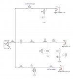
I'm at the stage now with Xsim and crossover design where I have a decent grasp of the necessary concepts. But, I have been following a couple threads of late where Diyaudio members @Douglas Blake and @jReave have made to compelling post that has me thinking I don't know that much after all.😀 So, in the pursuit to dive further into learning more advance uses of Xsim and crossover design in general; I have attached some screenshots of a current 3 way speaker that has been my winter project. Also, I have included the Xsim .dxo file so others can play along as well. Sometime later today, I will take a couple photos of the one speaker that is completed. The other is in the final stages of french polish shellac and needs maybe 1 more week (hopefully).🙂
The inspiration/ idea for this build came from Paul Carmody's Tarkus design.
Selected drivers:
Woofer- Peerless SLS 830668 (65 Liter VB) ported
Mid range- B&C 6NDL38
Tweeter- SS D2604/833000 w/ Monacor WG300
Thanks in advance! This will be fun learning experience.😀
The inspiration/ idea for this build came from Paul Carmody's Tarkus design.
Selected drivers:
Woofer- Peerless SLS 830668 (65 Liter VB) ported
Mid range- B&C 6NDL38
Tweeter- SS D2604/833000 w/ Monacor WG300
Thanks in advance! This will be fun learning experience.😀
Attachments

Hello Montana ...
This should be interesting!
But first I should probably clarify a few things for you... I am by no means the world's expert on crossovers. I generally get the job done but not always in the most "advanced" ways. In fact I tend to pull back to old school thinking in many cases. The advantage I may have over some of the other guys is that I have a solid base in electronics theory, going back to my teens (and that was a looong time ago).
One of the reasons I keep jumping into these threads is that in my retirement-business (before the virus killed it) I was being asked to look into loudspeakers that either didn't have that zing or were behaving badly in people's rooms. Often as not I would discover a well made cabinet, decent drivers and a crossover so complex that, in my day, only a fool would build it. This results in inefficient speakers where a lot of the amplifier's current is simply re-routed to ground and of course that makes the amplifiers run hotter. In one case --the one that started all this-- it killed a $600 amp a week after hooking it up.
Keep in mind, I'm not just talking about DIY projects gone wrong... I'm including consumer grade speakers, with well known names on them.
What I was seeing was evidence that "designers" didn't really understand what they were designing and, using simulators like XSim, were designing crossovers like they were playing with lego... just throwing parts at it until they got what they wanted.
When I got onto a couple of other DIY boards hoping to gain some insight about this trend, I discovered much the same problem... half the guys promoting themselves as "experts" didn't even know what a capacitor does, what a coil does, etc. they just saw them as lego blocks to be played with in simulators and they were building crossovers that clearly reflected this lack of underlying knowledge.
All that said...
When I design anything I have a number of goals in mind...
1) It has to work. (obviously)
2) It should be as simple as possible to accomplish #1
3) It needs to be as efficient as possible without sacrificing #1 or 2
4) Failure modes are considered (no fun if it burns down the house)
5) It has to be repairable.
So there it is... enough said, that's me in this context...

@Douglas Blake,
I really like your approach to crossover design. I’m very interested in learning about the entire chain. For me, I would like gain a better understanding of what facets of crossover design is worth obsessing over and what is not. It has become increasingly clear to me that one chain sit for hours and fiddle with a simulation but at what point should that be aborted. Just by example, the Xsim schematic that I attached does not display very good phase tracking at the crossover points. But, I have noticed in measuring speakers with built crossovers in place several instances those that simulated with poor phase tracking measured great and just the opposite has been observed. So, one question among many, is this something to get overly concerned with in the simulation process or just get reasonable close and than actually check with measurement mic?
Best Regards,
Rich
Okay ... now on to your design...
First, let me say I've seen far worse...
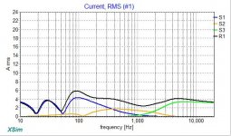
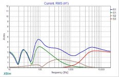
The first current panel with the amplifier output jacked up (because XSim doesn't resolve to less than an amp) shows some inefficiency. Note that the Total Current (blue) is almost always greater than the sum of the drivers below it... For example at just over 100hz you have about 6 amps flowing, but only about 4 of that is actually getting to your woofer (green), then at just under 2000 hz you have about 1 amp going through your mid (brown) and 1 amp going through your tweeter (red), but the total is nearly 4 amps, not 2 as expected.
So the question is... where is the rest of it going?
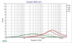
Well, if it's not going through drivers, it must be going to ground (in the schematic) where it's returned to the amplifier. My goal would be to minimise this as much as possible. The second current panel shows the currents in your shunt components (going to ground)... Here you can see that at least L3 and C3 could be a problem.
In a 100 watt amp at 8 ohms we should expect no more than about 3.5 amps total current flowing, if we aren't to cause some extra heat. There is a nice little calculator HERE to help you with the math.
So there it is ... a look at crossover efficiency... hope that helps.
First, let me say I've seen far worse...
The first current panel with the amplifier output jacked up (because XSim doesn't resolve to less than an amp) shows some inefficiency. Note that the Total Current (blue) is almost always greater than the sum of the drivers below it... For example at just over 100hz you have about 6 amps flowing, but only about 4 of that is actually getting to your woofer (green), then at just under 2000 hz you have about 1 amp going through your mid (brown) and 1 amp going through your tweeter (red), but the total is nearly 4 amps, not 2 as expected.
So the question is... where is the rest of it going?
Well, if it's not going through drivers, it must be going to ground (in the schematic) where it's returned to the amplifier. My goal would be to minimise this as much as possible. The second current panel shows the currents in your shunt components (going to ground)... Here you can see that at least L3 and C3 could be a problem.
In a 100 watt amp at 8 ohms we should expect no more than about 3.5 amps total current flowing, if we aren't to cause some extra heat. There is a nice little calculator HERE to help you with the math.
So there it is ... a look at crossover efficiency... hope that helps.
Attachments
Last edited:
@Douglas Blake,
I really like your approach to crossover design.
Thanks ... but lets see if that changes along the way 😉
I’m very interested in learning about the entire chain. For me, I would like gain a better understanding of what facets of crossover design is worth obsessing over and what is not. It has become increasingly clear to me that one chain sit for hours and fiddle with a simulation but at what point should that be aborted.
This is where a better theoretical understanding of each part's behaviour is helpful... For example I can usually predict what changing a part value will do, which is a real time saver.
Doesn't mean I don't go down dead ends from time to time, but at least I can avoid the obvious ones.
Just by example, the Xsim schematic that I attached does not display very good phase tracking at the crossover points. But, I have noticed in measuring speakers with built crossovers in place several instances those that simulated with poor phase tracking measured great and just the opposite has been observed. So, one question among many, is this something to get overly concerned with in the simulation process or just get reasonable close and than actually check with measurement mic?
XSim does a pretty good job of predicting the output, so what you can expect --without room or cabinet effects-- is pretty close.
I see speakers as "broad stroke" devices. I don't worry about a db here or a few degrees there so long as the overall effect is pretty close to what I'm looking for. Always keep in mind that no matter what anyone tells you, the human ear is a very inaccurate measuring device, so as long as we are "close enough" most designs will be just fine.
For those who are new at this...If you want to learn more about how capacitors coils etc. behave in circuits here's a very simple test jig in XSim....
Set up the panels as the thumbnail shows and play with the values of C1 and C2 you can see their behaviour in the graphs, both as series and as shunt components. Now replace them with coils and play with their values and see the effect.
The rules are pretty basic...
Capacitors conduct more as frequency increases
Inductors conduct less as frequency increases
Resistors conduct evenly at all frequencies.
These three basic facts are the root of all crossover design.
Attachments

Last edited:
Thanks so much @Douglas Blake,
I will try to sit down this evening and apply some of the design thoughts/ principles that you have outlined. Let’s see if we can get a very efficient and amp friendly design going.
Best,
Rich
I will try to sit down this evening and apply some of the design thoughts/ principles that you have outlined. Let’s see if we can get a very efficient and amp friendly design going.
Best,
Rich
First thought is that you should do something about the 4k breakup of the mid, I'm thinking RC in parallel with L2.
The raw FR of the tweeter looks a bit odd to me. I have a similar tweeter in the WG300(The Typhany version) and it did not measure like that. Is the tweeter properly installed in WG and on baffle? Did you make the adapter between tweeter and WG?
Test | Scan-Speak Discovery D2604 / 833000
The raw FR of the tweeter looks a bit odd to me. I have a similar tweeter in the WG300(The Typhany version) and it did not measure like that. Is the tweeter properly installed in WG and on baffle? Did you make the adapter between tweeter and WG?
Test | Scan-Speak Discovery D2604 / 833000
Thanks so much @Douglas Blake,
I will try to sit down this evening and apply some of the design thoughts/ principles that you have outlined. Let’s see if we can get a very efficient and amp friendly design going.
Best,
Rich
I will try to sit down this evening and apply some of the design thoughts/ principles that you have outlined. Let’s see if we can get a very efficient and amp friendly design going.
Best,
Rich
@Rallyfinnen,
I will look at adding RC in parallel with L2 and see if I can squash some of the mid breakup.
As for the tweeter w/ waveguide issue, I don't know what to say. I have an adapter installed between the tweeter and waveguide as per Troels Gravesen instructions on his website. Everything appears to be mounted correctly on baffle.
Best,
Rich
Just quickly here, I'm pretty much in complete agreement with Douglas. I don't have the electronic background that he does so I have found his insights both helpful and quite interesting.
Where we differ a little I think is in where we are willing to make compromises. In practical terms, I think I'm willing to accept a xo that is a little more inefficient that he is if it gets me closer to some of my other goals.
As a method of using this current information (so to speak - ok I know that was really bad 😀), I might suggest the following guidelines:
1 - determine how many watts you need to reach the woofer's xmax or to achieve your maximum desired SPL or the maximum power the woofer is rated for, whichever comes first or whichever is your most important goal.
2 - work out your xo to the best of your ability keeping your eye out in particular for small inductor values in the parallel legs of your HP filters and very large capacitor values in your LP filters parallel legs. Any other parallel components may need close attention as well, so for example a tanking capacitor in parallel with a series inductor.
3 - now feed the XSim Power Amp the maximum watts that you determined you will be using in step 1.
4 - determine what the maximum current your amp is actually capable of. Douglas gave you a good link I think or you could just use the equation, I = sqrt (P/R). So 100W (P) into 4ohm (R) will have a max current (I) of 5amps just as an example.
5 - now check out XSim's Current graph. Are any of your drivers or components drawing more than what your amp is capable of? If so, you've got 3 choices: a) re-work your xo to lower the current draw (probably the best choice) or b) get a more powerful amp which will give you more current as well or c) don't play the things so gosh darn loud!
6 - Be sure that your amp has some headroom as well, 3dB for sure but probably 6dB minimum is best.
*Disclaimer: as this is slightly new to me, I reserve the right to change any or all of the above at any time due to my own ignorance. 😛
As for the rest of your xo, I'll have a closer look at it now and get back to you.
Hi jReave,
Thanks for chiming in! I will look to incorporate the items you mentioned. I would dearly like to have a closer look at my crossover design, but I must return to work. Maybe this evening I can give it a look see.
Best Regards,
Rich
Thanks for chiming in! I will look to incorporate the items you mentioned. I would dearly like to have a closer look at my crossover design, but I must return to work. Maybe this evening I can give it a look see.
Best Regards,
Rich
@Jreave ...
Just so we're on the same page ... I'm used to calling a part in series with a driver an "inline" part. I generally refer to parts across a driver or connected to ground as "Shunt" parts.
For me "Parallel" means two or more parts hooked together side by side.
Just for clarity...
Thanks for joining in...
Copy that!
Just so we're on the same page ... I'm used to calling a part in series with a driver an "inline" part. I generally refer to parts across a driver or connected to ground as "Shunt" parts.
For me "Parallel" means two or more parts hooked together side by side.
Just for clarity...
Thanks for joining in...
c) don't play the things so gosh darn loud!
Copy that!
Last edited:
Hi jReave,
Thanks for chiming in! I will look to incorporate the items you mentioned. I would dearly like to have a closer look at my crossover design, but I must return to work. Maybe this evening I can give it a look see.
Overall ... any part that is not passing current into a driver is wasting energy. Wasted energy causes unnecessary heat either in your crossover or the amplifier.
@Douglas Blake,
Yea....I have noticed that in my preliminary testing. I tried to address the mid range breakup with a RC tank over L2 as @Rallyfinnen suggested but current looks like it has a runaway.😱
Would you be inclined to avoid overuse of second or third order filters with components going to ground? If so, how do you achieve steeper roll offs where necessary?
Best,
Rich
@Douglas Blake,
Yea....I have noticed that in my preliminary testing. I tried to address the mid range breakup with a RC tank over L2 as @Rallyfinnen suggested but current looks like it has a runaway.😱
When a circuit passes through (or is operated at) it's resonant frequency, eddy currents between the components will actually make their own current... and that could be audible.
Would you be inclined to avoid overuse of second or third order filters with components going to ground? If so, how do you achieve steeper roll offs where necessary?
I'm not opposed to anything that works.
The first question is whether the breakup is at a level where it would be audible... If not I'd be less worried about that then getting good frequeny response and efficient operation.
Glitch (my avatar) would say: "KISS ... Keep it stupidly simple"
Hey Rich,
I've a look at things and here are my 1st reactions:
1 - Turn off the system phase in the FR graph. It tells you nothing and just adds to the visual confusion.
2 - Get in the habit of always choosing the same colors for your drivers. Again, it lessens confusion. From my time working with PCD, I always choose black for the system response, red for the tweeter, blue for the woofer and the pinkish purple for the mid. Make your own choices of course but I suggest try to be consistent.
3 - Also for less confusion, I'd suggest formating the xo schematic with the tweeter at top and woofer at bottom. It's more natural for me to look at it this way anyways.
4 - It took me a few minutes to figure out that you are using real measured responses and not simulations. Excellent. But that's a strange result for the woofer. The dip at 150Hz and then the sort of raised plateau right after it makes me wonder if you have blended near and farfield measurements correctly?
5 - Regardless, when I looked at the sim, the 1st thing I saw was a problem with the woofer and mid xo. Way too much contribution from each on either side of the xo point. The woofer is actually only about 15dB down when it crosses the tweeter response.
So what I think will help you is to use target slopes. What I do is go to another piece of software to create them and then I import them into XSim via unconnected drivers. I use Response Modeler to do so which unfortunately requires Excel which not everybody has access to. Maybe there's an easier way to get them into XSim but I'm not sure what that is. Perhaps someone else may be of help on that point.
However before you can do that, you have to decide on your xo points and roll-off slopes which means taking a good look at your drivers. The Peerless woofer is pretty simple as it's been used so successfully in the Tarkus with a 400Hz xo point. Second order acoustic should be fine. That looks like it works too for the HP on the mid.
The tweeter on the other hand has rising distortion and increasing cone resonance below about 2000Hz (courtesy of Zaph again) and the mid looks like it has a vicious resonant peak at about 4000Hz. Unfortunately the mid fails to provide off-axis measurements but given its size, I think 2000Hz would be a maximum to aim for. Given that, I think your choice of about 1800Hz is bang on but I would go LR4 acoustic slopes to be safe and I would notch that mid resonance one way or another. But given this lowish xo point, 400Hz as the other one now strikes me as a little high (ie. not very much contribution from the mid actually), so I might reduce the lower xo point to about 300Hz.
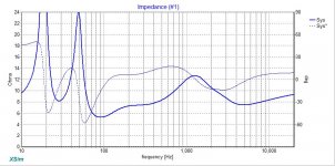
Something else to note is the rather high impedance peak on the mid. Nothing wrong with this per se but when you try to add a HP filter to it for a mid in a 3-way, you can often get a reaction that increases the output at that resonant frequency. I'm not sure yet but an impedance compensation filter may be required on the mid. Or sometimes just a lone shunt resistor of sufficient value can do the trick as well.
Also I'm a little surprised that after modeling the design after the Tarkus you decided not to use the same proven filter on the woofer. Give it a go and see what happens.
To help out, I've attached a new version of XSim with the Target filters included and the tweeter put up at the top. For the Target curves, enable the 'driver only' choices in the FR graph for the new drivers you'll see on the left side of the of the xo schematic. Choose the same color for them all as I think that's easier on the eyes. Notice that I've manipulated the Power amp a touch so your fundamental is properly lined up with the targets.
Finally, all the curves and lines can be visually overwhelming with a bigger design. Nothing says you have to have them all displayed at the same time though. If you're working on the lower xo, turn off the tweeter and the lower xo targets, and likewise the woofer and the woofer/mid targets when you are working on the mid/tweeter xo.
Hope that helps. Now I'll give the actual xo a go.
I've a look at things and here are my 1st reactions:
1 - Turn off the system phase in the FR graph. It tells you nothing and just adds to the visual confusion.
2 - Get in the habit of always choosing the same colors for your drivers. Again, it lessens confusion. From my time working with PCD, I always choose black for the system response, red for the tweeter, blue for the woofer and the pinkish purple for the mid. Make your own choices of course but I suggest try to be consistent.
3 - Also for less confusion, I'd suggest formating the xo schematic with the tweeter at top and woofer at bottom. It's more natural for me to look at it this way anyways.
4 - It took me a few minutes to figure out that you are using real measured responses and not simulations. Excellent. But that's a strange result for the woofer. The dip at 150Hz and then the sort of raised plateau right after it makes me wonder if you have blended near and farfield measurements correctly?
5 - Regardless, when I looked at the sim, the 1st thing I saw was a problem with the woofer and mid xo. Way too much contribution from each on either side of the xo point. The woofer is actually only about 15dB down when it crosses the tweeter response.
So what I think will help you is to use target slopes. What I do is go to another piece of software to create them and then I import them into XSim via unconnected drivers. I use Response Modeler to do so which unfortunately requires Excel which not everybody has access to. Maybe there's an easier way to get them into XSim but I'm not sure what that is. Perhaps someone else may be of help on that point.
However before you can do that, you have to decide on your xo points and roll-off slopes which means taking a good look at your drivers. The Peerless woofer is pretty simple as it's been used so successfully in the Tarkus with a 400Hz xo point. Second order acoustic should be fine. That looks like it works too for the HP on the mid.
The tweeter on the other hand has rising distortion and increasing cone resonance below about 2000Hz (courtesy of Zaph again) and the mid looks like it has a vicious resonant peak at about 4000Hz. Unfortunately the mid fails to provide off-axis measurements but given its size, I think 2000Hz would be a maximum to aim for. Given that, I think your choice of about 1800Hz is bang on but I would go LR4 acoustic slopes to be safe and I would notch that mid resonance one way or another. But given this lowish xo point, 400Hz as the other one now strikes me as a little high (ie. not very much contribution from the mid actually), so I might reduce the lower xo point to about 300Hz.
Something else to note is the rather high impedance peak on the mid. Nothing wrong with this per se but when you try to add a HP filter to it for a mid in a 3-way, you can often get a reaction that increases the output at that resonant frequency. I'm not sure yet but an impedance compensation filter may be required on the mid. Or sometimes just a lone shunt resistor of sufficient value can do the trick as well.
Also I'm a little surprised that after modeling the design after the Tarkus you decided not to use the same proven filter on the woofer. Give it a go and see what happens.
To help out, I've attached a new version of XSim with the Target filters included and the tweeter put up at the top. For the Target curves, enable the 'driver only' choices in the FR graph for the new drivers you'll see on the left side of the of the xo schematic. Choose the same color for them all as I think that's easier on the eyes. Notice that I've manipulated the Power amp a touch so your fundamental is properly lined up with the targets.
Finally, all the curves and lines can be visually overwhelming with a bigger design. Nothing says you have to have them all displayed at the same time though. If you're working on the lower xo, turn off the tweeter and the lower xo targets, and likewise the woofer and the woofer/mid targets when you are working on the mid/tweeter xo.
Hope that helps. Now I'll give the actual xo a go.
Attachments
@jReave,
Thanks for your very detailed direction.😀 I will arrange things a little neater moving forward.🙂
As for the odd 150 hz. dip in woofers response, It probably is my method in measuring nearfield response. I may need to place mic inside the box since dual ports on front of baffle are close enough to woofer that arriving at a realistic measurement has been difficult. Can I generate a low frequency model in something like Unibox and use that instead of a measurement?
Oh. Btw, I did not see where you attached the Xsim file you mentioned.
Best,
Rich
- Home
- Loudspeakers
- Multi-Way
- Xsim Critique- taking it to the next level