Wow, you have me beat as I have 250 and I thought that was lot 🙂
Probably can do it in 25 from same batch to within 1%
Now you need to match IRF610's. You probably know but 3-pin 5mm pitch screw terminal blocks hold TO220 3-legged creatures very well for such testing.
When I built the PCA I measured and tested, ~50 IIRC. I had several very tight matches from that batch. If I'm lucky, they're still labeled in their bins.... ha.
Match the IRF610's for VGS?
Vgs should be good enough. Even better is same way I matched the ZVNs - in-situ with full circuit and match by the bias current produced. That's probably not necessary.
Is there any problems buying BF862s from ebay sources?
I’ve bought quite a few from ebay. They’re so cheap, it seems to me that there’s no real money to be made faking them.
I could be wrong though......
eBay or Aliexpress is fine for BF862's. They are not worth faking. Right now, they are EOL so not in stock at major companies anymore.
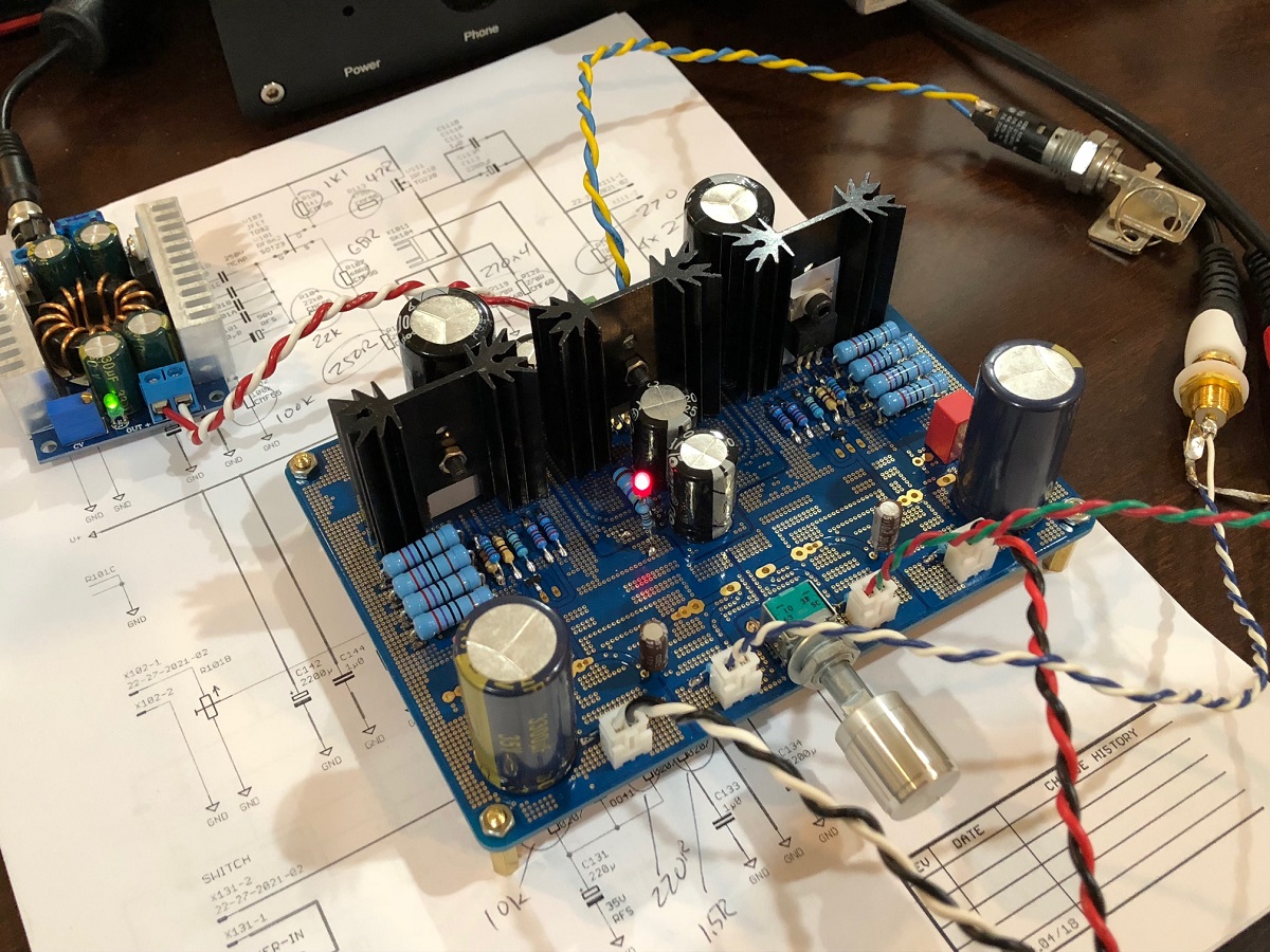
Good news, I built and verified the new Desktop Class A (DCA) amp. It works well and sounds great. An easy build.
I am using a DC step up to get exactly 20v at the amp after the Cap Mx. Running 130mA bias current:
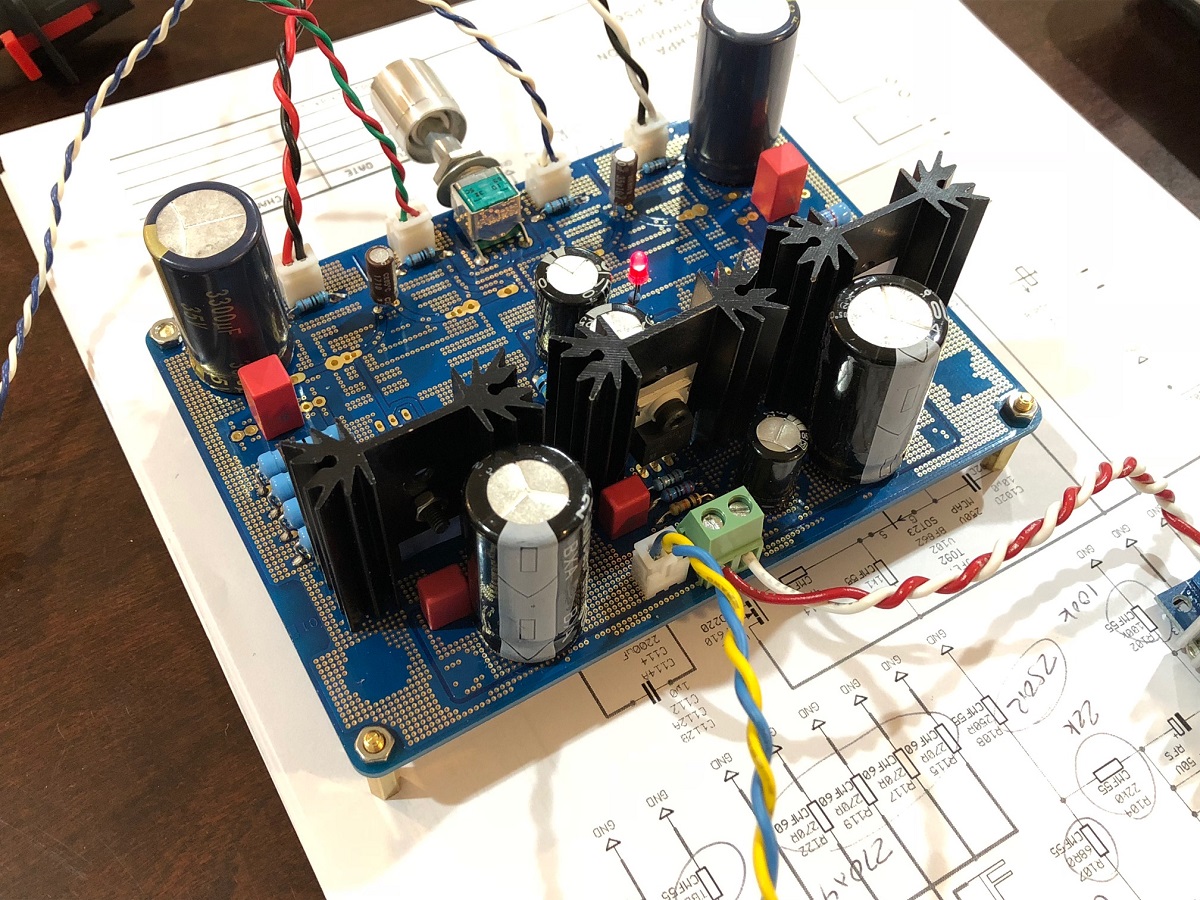
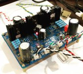
Here is the backside so you can see the parts behind the heatsink:
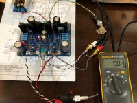
Here is measuring the noise at the output with my Fluke 101 on mVrms and I get 0mV. It sounds quiet as well.
Will have to stop now and listen tomorrow. Just two songs so far to confirm PCB is good and free of itcner
Good news, I built and verified the new Desktop Class A (DCA) amp. It works well and sounds great. An easy build.
I am using a DC step up to get exactly 20v at the amp after the Cap Mx. Running 130mA bias current:
Here is the backside so you can see the parts behind the heatsink:
Here is measuring the noise at the output with my Fluke 101 on mVrms and I get 0mV. It sounds quiet as well.
Will have to stop now and listen tomorrow. Just two songs so far to confirm PCB is good and free of itcner
Attachments

Last edited:
Yes, because it is the very last "switch" I have on hand in my supplies. Looks cool but could be problematic is one loses the key. 🙂
It's a very simple build as you can see - hardly any parts except for the 4 parallel 2w resistors for the resistive load.
We forgot to ask JPS64 to include an LED power on indicator so I added it after the Cap Mx so we can see that the PSU in functional.
It's a very simple build as you can see - hardly any parts except for the 4 parallel 2w resistors for the resistive load.
We forgot to ask JPS64 to include an LED power on indicator so I added it after the Cap Mx so we can see that the PSU in functional.
Yes, because it is the very last "switch" I have on hand in my supplies. Looks cool but could be problematic is one loses the key. 🙂
It's a very simple build as you can see - hardly any parts except for the 4 parallel 2w resistors for the resistive load.
We forgot to ask JPS64 to include an LED power on indicator so I added it after the Cap Mx so we can see that the PSU in functional.
haha, losing the key would be a pain.
Looks like an easy build, I'm ordering some parts now. Likely use all Takman REY 1/4w, and mills mra5 for the sets of parallel resistors.
I scrounged together enough good resistors last night to make a 10k stepped attenuator, takman, irc rn60's, and a few kiwames. Depending on time though, I may just use an alps for now.
I could see you taking the circuit to your local locksmith asking for a new key to turn on the amp!!
I build a desktop version using the Pocket circuit board, this is so much nicer, now I must order a new board. You guys are killing me here!!
All fun though.
I build a desktop version using the Pocket circuit board, this is so much nicer, now I must order a new board. You guys are killing me here!!
All fun though.
Board just ordered X. I am guessing X, I can remove some of the parts from the PCA and reuse them.
Board just ordered X. I am guessing X, I can remove some of the parts from the PCA and reuse them.
The parts are so cheap, you should leave the other as is, it sounds great doesn't it? Use this one for your special low impedance headphones or maybe use big fat boutique caps? 3 x IRF610's, 2 x BF862's and a handful of resistors and caps. Get the heatsinks from Jameco for $9/10.
To-220 Heat Sink 1 Hole 10 Pcs | eBay
Thanks for the order!
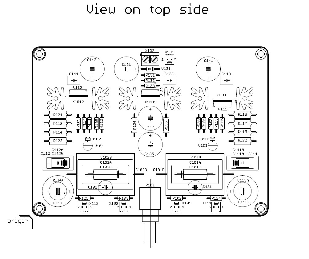
This drawing was key to stuffing it, and it worked the first time no issues. You can check to make sure it works by measuring the bias current across the 4x 270R resistor arrays. Depending on voltage on Vcc, it can be about 8v (18v), 9v (20v), 10v (22v). I am running 20v for 9v/67.5R=133mA. It's warm but not bad at all.
I am using large 10,000uF 25v rail smoothing caps on C141/142 (because I had them). Big values here ensure great stereo separation. The CRC caps are 2200uF 35v. For output coupling I am using Panasonic FC 3300uF 35v (because I had them) bypassed with Wima 4.7uF MKS. For input caps a simple 10uF 35v Silmic II, no film bypass. I actually had all parts in my supply bins and did not have to buy anything extra to make this amp. All IRF610's are genuine Vishay from same tube and transistor tester showed same Vgs.
Last edited:
Are those the same heatsinks you used on dados pre/headphone amp.The parts are so cheap, you should leave the other as is, it sounds great doesn't it? Use this one for your special low impedance headphones or maybe use big fat boutique caps? 3 x IRF610's, 2 x BF862's and a handful of resistors and caps. Get the heatsinks from Jameco for $9/10.
To-220 Heat Sink 1 Hole 10 Pcs | eBay
Thanks for the order!
This drawing was key to stuffing it, and it worked the first time no issues. You can check to make sure it works by measuring the bias current across the 4x 270R resistor arrays. Depending on voltage on Vcc, it can be about 8v (18v), 9v (20v), 10v (22v). I am running 20v for 9v/67.5R=133mA. It's warm but not bad at all.
I am using large 10,000uF 25v rail smoothing caps on C141/142 (because I had them). Big values here ensure great stereo separation. The CRC caps are 2200uF 35v. For output coupling I am using Panasonic FC 3300uF 35v (because I had them) bypassed with Wima 4.7uF MKS. For input caps a simple 10uF 35v Silmic II, no film bypass. I actually had all parts in my supply bins and did not have to buy anything extra to make this amp. All IRF610's are genuine Vishay from same tube and transistor tester showed same Vgs.
So with some more listening, I think I have a few minor tweaks the DC setpoints that sound nicer. It sort of depends on your specific BF862 and how much gain it has. I am finding that R107/R111 set at 56R and R108/R112 set at 220R seems to give me a bit better dynamics and overall sound quality.
Last edited:
Running really well and superb sounding. Measuring in at 0.015% THD all H2/H3 and powerful deep bass with 150mA buss at 22v rail. Dissipating about 2w per channel.
I want to mention that this is a really really easy build. An ideal first project or gift for someone new to DIYA.
I want to mention that this is a really really easy build. An ideal first project or gift for someone new to DIYA.
Attachments
Last edited:
I can slip in a few for you before the postman comes. 🙂 consider it done.
haha thanks for that 😀
what step up are you using to power it? Looks beefier than the one for the pocket version.
I shall get started on finding the parts later today. was planning to have the PCB "bare" so may have to find a way to mount some jacks onto the board
haha thanks for that 😀
what step up are you using to power it? Looks beefier than the one for the pocket version.
I shall get started on finding the parts later today. was planning to have the PCB "bare" so may have to find a way to mount some jacks onto the board
Something like this works well - the blue ones seem better than the red ones, in my experience.
DC-DC Converter 10/12/15/20A 150/250/300/400/1200W Step up Step down Buck Boost | eBay
Search eBay or Aliexpress for "DC DC step up 10 amp"
Some Measurements of the DCA
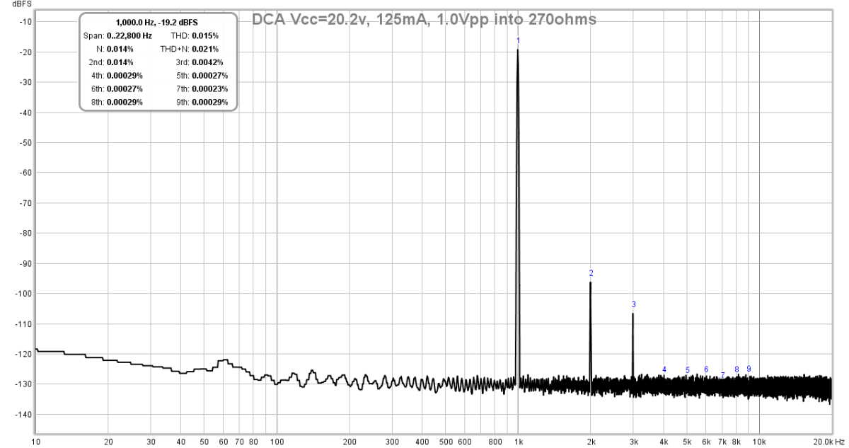
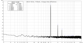
This is with the 56ohm/220hm mod on the resistor network as described above. I found that the harmonic profile can be tuned with the Vcc setting. There is even a point where you can make it H3 dominant. But to do this requires looking at real time FFT and adjusting the Vcc. I have found that the ideal harmonic profile lies right around the design voltage Vcc=20v, and with FFT monitor, it is 20.2v to be precise but this varies for each amp due to variations in the actives.
Source was a Cayin N3 DAP loaded with a high res 1kHz sine wave. The FFT was measured with a Focusrite 2i4 at 48kHz. Load resistor is built in 270ohm at output JST pins.
For 20.2v Vcc, 125mA bias, I get 0.015% THD and this profile:
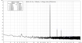
If you like it more tubey sounding with higher relative H2, set to lower voltage of 19.5v and THD is 0.03%:

If you like really low overall THD of 0.0066% and about the same H2 and H3, set to higher voltage of 21.3v:

So having a variable DC-DC step up is really useful. We can see that the design of the PSU is working well to really keep the 60Hz peak low. The overall amp layout design is excellent and sounds very good. Extremely low noise. The slight rise in the FFT towards 0Hz is due to a large 10uF input coupling cap that is letting infrasonic noise through. Uses of 4.7uF input cap would reduce that - not that it is audible.
This is with the 56ohm/220hm mod on the resistor network as described above. I found that the harmonic profile can be tuned with the Vcc setting. There is even a point where you can make it H3 dominant. But to do this requires looking at real time FFT and adjusting the Vcc. I have found that the ideal harmonic profile lies right around the design voltage Vcc=20v, and with FFT monitor, it is 20.2v to be precise but this varies for each amp due to variations in the actives.
Source was a Cayin N3 DAP loaded with a high res 1kHz sine wave. The FFT was measured with a Focusrite 2i4 at 48kHz. Load resistor is built in 270ohm at output JST pins.
For 20.2v Vcc, 125mA bias, I get 0.015% THD and this profile:
If you like it more tubey sounding with higher relative H2, set to lower voltage of 19.5v and THD is 0.03%:
If you like really low overall THD of 0.0066% and about the same H2 and H3, set to higher voltage of 21.3v:
So having a variable DC-DC step up is really useful. We can see that the design of the PSU is working well to really keep the 60Hz peak low. The overall amp layout design is excellent and sounds very good. Extremely low noise. The slight rise in the FFT towards 0Hz is due to a large 10uF input coupling cap that is letting infrasonic noise through. Uses of 4.7uF input cap would reduce that - not that it is audible.
Attachments
Last edited:
X,
Nice project, build looks straightforward. JP's PCB looks neat. Measurements are in line with your design goals. Great work as usual! 🙂
Nice project, build looks straightforward. JP's PCB looks neat. Measurements are in line with your design goals. Great work as usual! 🙂
Beautiful, simple circuit and exquisitely laid out by JPS64.
Congratulations to both of you....... maybe three? Who is BDMH?
Hugh
Congratulations to both of you....... maybe three? Who is BDMH?
Hugh
Last edited:
- Home
- Group Buys
- xrk971 Pocket Class A Headamp GB