Yes, I just received the shipment of boxes yesterday. Now comes the packing and shipping. I need to make bags with all the included connectors (2x 6pin Molex Minifit Jr, 1x Molex 4pin Minifit Jr, 2x Molex KK 3pin for balanced audio input, all crimp connector inserts.
Hopefully will send out first batch tomorrow. Will have them all sent out by Saturday for sure.
Hopefully will send out first batch tomorrow. Will have them all sent out by Saturday for sure.
First batch of half of the amps ordered are now waiting for pickup by USPS. Working on orders based on FIFO. I need to re-supply the 6pin Molex Minifit connectors. That will take a few days to get here. If you did not yet receive a notice from Etsy/USPS that your package is on its way and don’t need the 6pin connectors (as the FASTON tabs are standard and already installed). Please send me message in Etsy or here and I’ll ship it right away.
Attachments

DARN! It looks like that guy second in the FIFO queue ordered 14! 😱
Guess Ill have to wait a little longer... 🙄
Guess Ill have to wait a little longer... 🙄
If not for the lack of Minifit 6pin jacks, I would have sent yours out. I ordered more 1-day shipping so should be here soon.
That's OK. I'm still waiting on the power supply also, so I won't be able to use it right away, anyway.
I originally went with the Connex Elect SMPS800 but two days after I ordered it you guys started recommending the SMPS630-SO from Micro-audio, so I've got one of them coming also. He's waiting for parts from China to complete it, but had to wait until Chinese New Year celebrations were over.
So, I'll have one of each. But then, I did order two amps.
I also need to finish my active crossover board layout to go with the amp, but I'm just waiting to see with connector will work best.
So, I'll have one of each. But then, I did order two amps.
I also need to finish my active crossover board layout to go with the amp, but I'm just waiting to see with connector will work best.
Hi folks, I have received a delayed shipment notice from Mouser (they say due to COVID19 processing delays). So I still do not have the Molex 6pin connectors yet. Hopefully, they will come in a few days. For those who have not received a shipment notice yet, please hold tight.
Thanks,
X
Thanks,
X
Hi Otto,
Please see your PM's or Email. I have converted a board to 4channel SE output mode for you.
Please see your PM's or Email. I have converted a board to 4channel SE output mode for you.
Mouser has delayed my last two orders, also. One is supposed to ship today. Newark, Sager, and Arrow didn't have any delays, however, so I had something to do.
4 Channel SE Output Mode
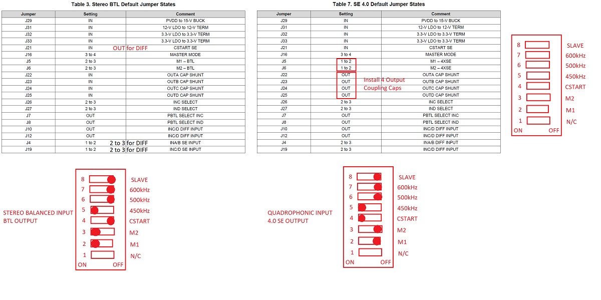
The amp has been converted for use as a 4 channel SE amp through addition of 4 output coupling caps (where the Faston tab jumpers are located). Althought the factory data sheet for the EVM recommends setting the M1 and M2 switches to "OFF" and "Cstart" to "ON" for 4 ch SE operation, I found that it actually works with the same settings for 2 ch balanced input and BTL output, with just the change in removing the Faston tabs and installing the 4x 1500uF 63v caps at the outputs. There are probably fine-print reasons why M1 and M2 should be set to "OFF" and it has to do with the phase of the outputs, so probably best to follow the datasheet advice.
A few things to note: the installation of the output caps interferes with the 6pin Molex Minifit Jr connector's locking tab/lever. A workaround is to cut off the lever with wire curtters and the connector can still work but lacks the locking feature. Or remove the 6pin Molex header and replace with 3 Faston tabs in the same holes.
The final caution is that in SE mode, the DC blocking output caps have to charge up to 1/2Vcc and this causes a speaker thump upon turn on (if recently turned off) - but not turn off. If one waits at least 15 seconds to allow the caps to discharge, there is no pop at turn on. So main thing is to not turn on immediately after powering off.
I do not have a 4 channel quadrophonic system so I simply connected 4 speakers and had them driven by a balanced source (out of phase and flipped one speaker's polarity to get all outputs in phase). It works and is able to drive 4 speakers simultaneously.
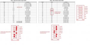
Here is a diagram of the DIP switch settings between BTL and 4Ch SE outputs:
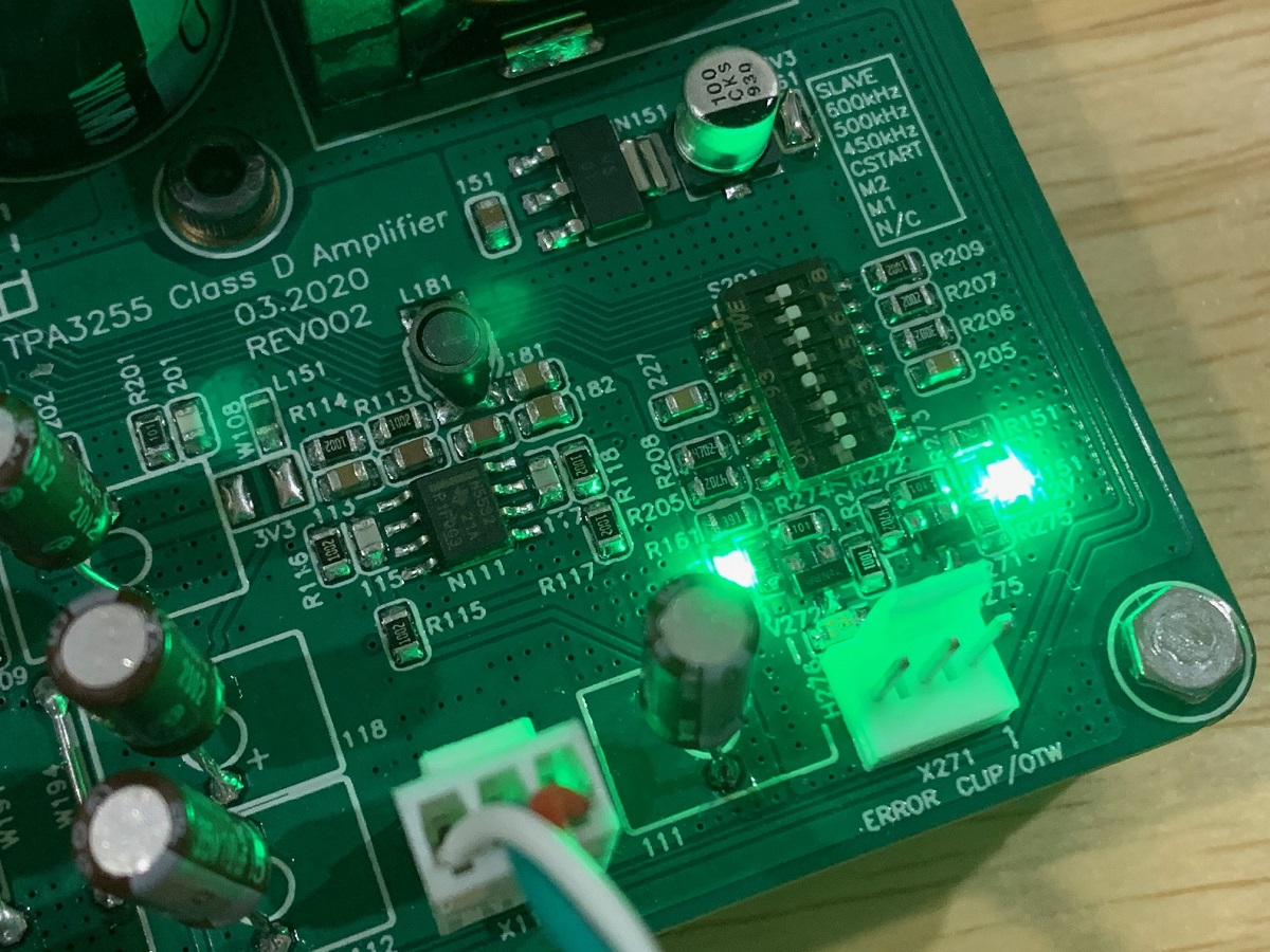
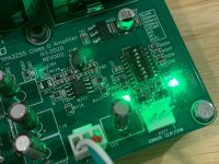
Here is a closeup of the DIP switch:
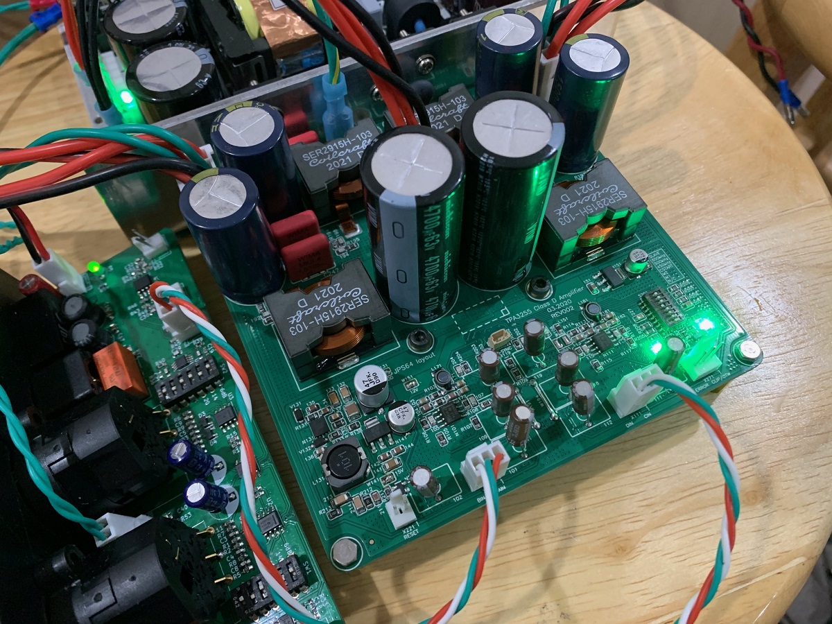
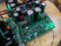
Here is the board with 4 extra caps and 4 speakers connected to the Molex 6pin Minifit connectors (the green wires are the ground returns for each channel):
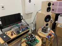
Here is the system playing with the 10F/RS225 FAST TL's and the 5.25in 2-way Rockville speakers:

So this looks like a good way to get 4 channels output for use with active speakers and DSP-based systems. To prevent turn on pop, something like the RTR SSR could be used, or even something like a mechanical relay based start delay circuit. There is no DC offset protection needed as the speaker is cap coupled.
It is easy enough to do yourself but if you would like the 4 Ch SE mod done for you, please send me a PM. The cost is $60.
The amp has been converted for use as a 4 channel SE amp through addition of 4 output coupling caps (where the Faston tab jumpers are located). Althought the factory data sheet for the EVM recommends setting the M1 and M2 switches to "OFF" and "Cstart" to "ON" for 4 ch SE operation, I found that it actually works with the same settings for 2 ch balanced input and BTL output, with just the change in removing the Faston tabs and installing the 4x 1500uF 63v caps at the outputs. There are probably fine-print reasons why M1 and M2 should be set to "OFF" and it has to do with the phase of the outputs, so probably best to follow the datasheet advice.
A few things to note: the installation of the output caps interferes with the 6pin Molex Minifit Jr connector's locking tab/lever. A workaround is to cut off the lever with wire curtters and the connector can still work but lacks the locking feature. Or remove the 6pin Molex header and replace with 3 Faston tabs in the same holes.
The final caution is that in SE mode, the DC blocking output caps have to charge up to 1/2Vcc and this causes a speaker thump upon turn on (if recently turned off) - but not turn off. If one waits at least 15 seconds to allow the caps to discharge, there is no pop at turn on. So main thing is to not turn on immediately after powering off.
I do not have a 4 channel quadrophonic system so I simply connected 4 speakers and had them driven by a balanced source (out of phase and flipped one speaker's polarity to get all outputs in phase). It works and is able to drive 4 speakers simultaneously.
Here is a diagram of the DIP switch settings between BTL and 4Ch SE outputs:
Here is a closeup of the DIP switch:
Here is the board with 4 extra caps and 4 speakers connected to the Molex 6pin Minifit connectors (the green wires are the ground returns for each channel):
Here is the system playing with the 10F/RS225 FAST TL's and the 5.25in 2-way Rockville speakers:
So this looks like a good way to get 4 channels output for use with active speakers and DSP-based systems. To prevent turn on pop, something like the RTR SSR could be used, or even something like a mechanical relay based start delay circuit. There is no DC offset protection needed as the speaker is cap coupled.
It is easy enough to do yourself but if you would like the 4 Ch SE mod done for you, please send me a PM. The cost is $60.
Attachments
Last edited:
Good news! My Mouser order from February 23rd is shipping out today. I'm sure they worked on my order first, because I'm a 'valued customer'. They should start working on your order now, X. 😀
You should get it last week. Apparently, they have a new Time Warp shipping engine. Here's the response I got: "To ensure that you receive your order on the day you expected it, Mouser has upgraded your order to ship ...". Kool!
You should get it last week. Apparently, they have a new Time Warp shipping engine. Here's the response I got: "To ensure that you receive your order on the day you expected it, Mouser has upgraded your order to ship ...". Kool!
My Mouser order came in today. I have packed up 3 more shipments (all double amp orders) going out today.
Ahtlcc,
You should have received a notification that yours is shipping today. 🙂
Ahtlcc,
You should have received a notification that yours is shipping today. 🙂
In case anyone is looking to get the same Micro-Audio SMPS that I am using, here is the link:
SMPS630-SO – MicroAudio
SMPS630-SO – MicroAudio
Mine arrived about a week ago. Unfortunately it will be a while before I can get started on it.
I got mine. I'm working on finding a suitable metal interface between the chip and my heatsink. Ideally, I'd like to use only a dab of thermal compound between the chip and the interface block, and a .5mm minus pad 8 (or similar) between that block and the large heatsink - maintaining electrical isolation. I need to go back through the thread to find the drawing of the milled block to get the exact dimensions. I have multiple large Copper and Aluminum heatsinks that can be used, but they don't have clearance for the SMT components on the bottom of the board.
I was hoping to power it up this weekend, but life got in the way. I would also like to find either the schematic or a drawing that shows the pinouts of the connectors on the board. At this point, just the 6 pin connectors on the corners and the tiny two pin connector below the TPA 3255 are unidentified by me. I'm sure they are in one of the threads. I've read most of the posts, but my memory isn't as great as it once was.
EDIT: The board looks great, BTW.
Last edited:
I used two AMP brand 0.250 Faston tabs (solid brass tin plated) as the thermal spacer to clear the SMT components. A small dab of thermal paste between the surfaces. Then all you need is a thermal block or heatsink with 36mm CTC M3 tapped threads to connect the heatsink to the chip thermal pad.
The connectors you need to use are the 4 pin Molex MiniFit Jr for power in. Take care to observe polarity (+ve is closest to the big caps). The installed Faston tabs labeled A/B/C/Dcan be used for speaker outputs with no further work. The audio inputs are the 3 pin Molex KK connectors. Look at the silk label to see which is A, B, C, D. The middle pin is ground.
The pins are B/GND/A and D/GND/C - the balanced input should drive A+/B- and C+/D- note that because the chip is on the bottom side, A and B come out the right side etc. it crosses in an X from front to back.
It helps to connect the PE tab to mains ground to reduce noise pickup.
That’s enough to get started.
- Home
- Group Buys
- XRK RTR TPA3255 Reference class D Amp GB2