300w is still a good deal for $14 device. Thanks for the link and the heads up on the limited capability.
I am told by the PCB assembly house in California that they will start either today or Monday. Hopefully will be completed by Wednesday next week. This is good news. 🙂
I pointed out this PSU in the other thread, but in case anyone is looking for a quiet SMPS, this is an excellent one. It has remote on/off via a simple small switch and also provides regulated always on 12v and 5v/3.3v for preamps and MCU's. Best of all, it does not suffer from start up in rush current shutdown as it can charge huge cap banks, and it is very quiet. Of all the SMPS I have tested, this one is the best - most features, quietest, and easy to use.
SMPS630-G – MicroAudio
SMPS630-G – MicroAudio
I pointed out this PSU in the other thread, but in case anyone is looking for a quiet SMPS, this is an excellent one. It has remote on/off via a simple small switch and also provides regulated always on 12v and 5v/3.3v for preamps and MCU's. Best of all, it does not suffer from start up in rush current shutdown as it can charge huge cap banks, and it is very quiet. Of all the SMPS I have tested, this one is the best - most features, quietest, and easy to use.
SMPS630-G – MicroAudio
Nutz, I just ordered the ConnexElectronic SMPS800RE two days ago!
What voltage would you recommend for the SMPS630-G? +-44 or +-55?
Yes, I agree from past experience. These SMPS units from MicroAudio/Cresnet are very nice.
Go with the 44v option, 53v is too close to the edge 😉
Go with the 44v option, 53v is too close to the edge 😉
I think 48v is a possibility. But 53v is too close to the edge as that’s the maximum the data sheet recommends. I ordered a custom 50v one.
Good news folks. The pick and place machine is now running and placing components on the first article. Then a few through hole items need to be soldered on. Hopefully we get a positive power up (two green LEDs and nothing orange glowing) and a good sound check. If all is good, the whole batch will be running through.
Great news! I am starting to prep. my amplifier chassis for this board now.
Thanks for the update. 🙂
Thanks for the update. 🙂
More good news folks. The first article tested without issue and plays music. We now begin full production of the rest of the amps.
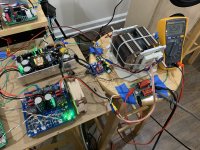
I redid some measurements of the TPA3255 amp last night with the new Micro-Audio PSU and new BTSB panel mount buffer board. I assembled a new dummy load resistor using two EBG UXP-300 10ohm resistors strapped to sandwich a 90mm PWM fan. One sucks and one blows. This way, I can have 10ohm or 5 ohm loads by simply connecting a bullet connector. The load resistor goes to a balanced voltage divider (10:1) and MKP coupling caps via an XLR cable. I found that the shield of the XLR, if connected via an 8d-20 NTC to chassis ground (SMPS frame/heatsink) the background noise goes down substantially.
Here is the test setup:

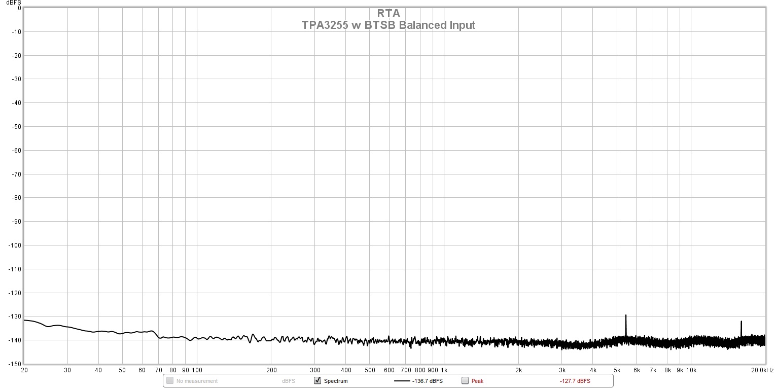
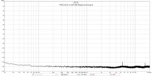
So first test is to see what the level of background noise the amp puts out with the balanced source connected via XLR to the BTSB v1.2p panel mount but no music playing. This will tell us "how black the blacks are". This amp is the champ when it comes to quietness. I have never measured anything else this quiet - it approaches my preamps or headphone amps:
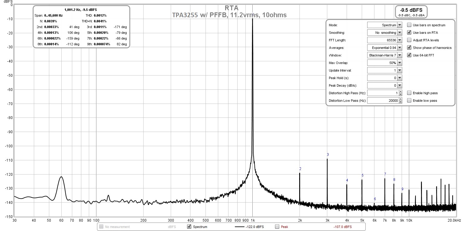
Next are some FFTs at verious levels of music playing. The Victors 1khz ppb oscillator source had to be connected via a single ended RCA cable, which picks up a bit of environmental 60Hz mains EMI. But the level is still very low.
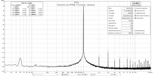
11.2vrms or 12.5w into 10ohms (0.0012% THD):
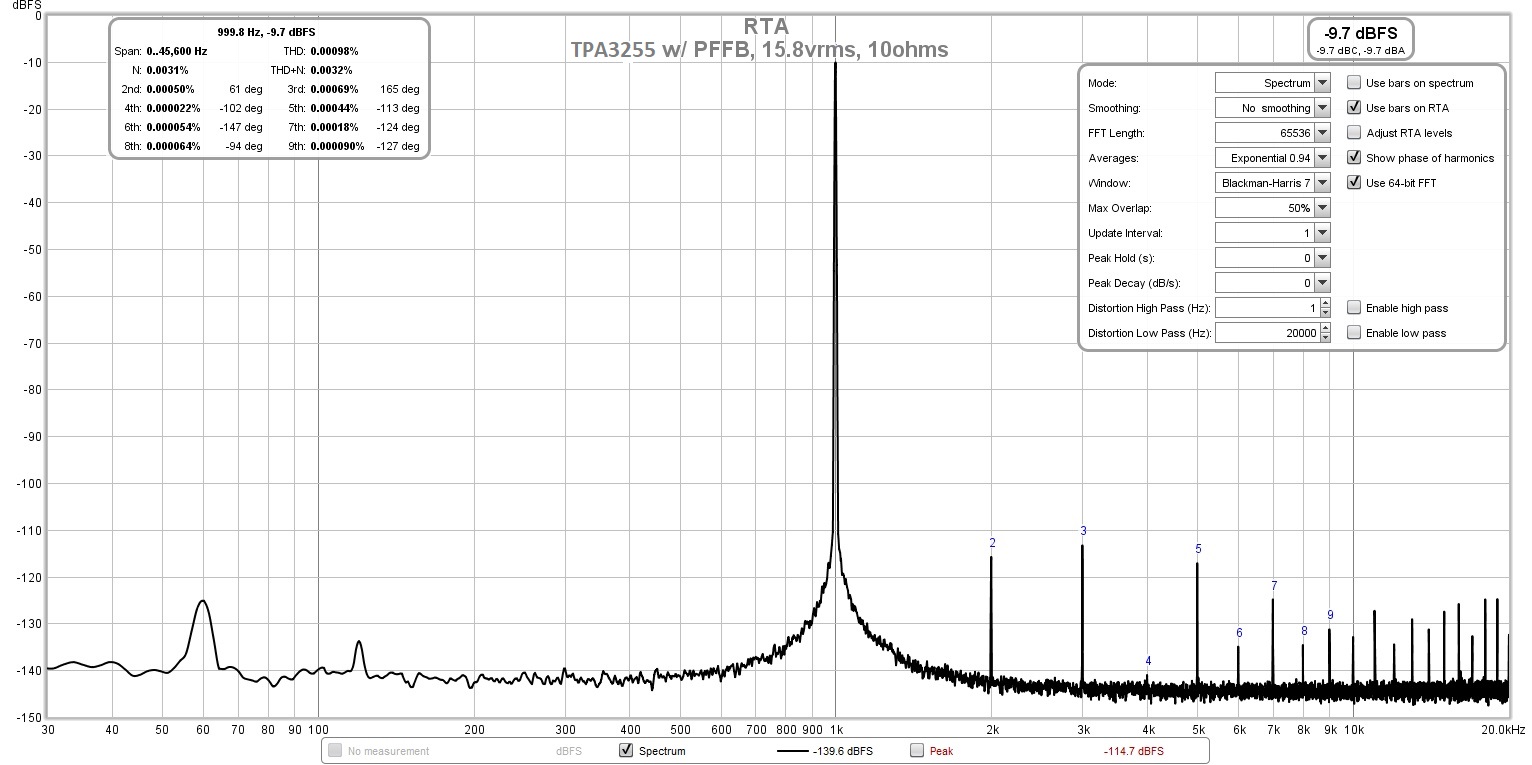
15.8vrms or 25w into 10ohms (0.00098% THD):
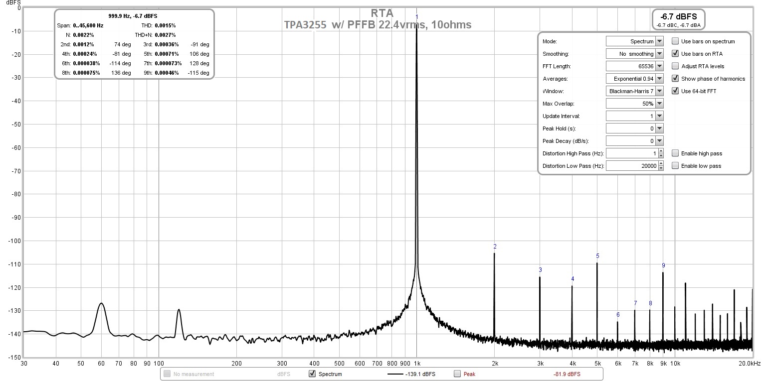
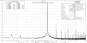
22.4vrms or 50w into 10ohms (0.0015% THD):
Here is the test setup:
So first test is to see what the level of background noise the amp puts out with the balanced source connected via XLR to the BTSB v1.2p panel mount but no music playing. This will tell us "how black the blacks are". This amp is the champ when it comes to quietness. I have never measured anything else this quiet - it approaches my preamps or headphone amps:
Next are some FFTs at verious levels of music playing. The Victors 1khz ppb oscillator source had to be connected via a single ended RCA cable, which picks up a bit of environmental 60Hz mains EMI. But the level is still very low.
11.2vrms or 12.5w into 10ohms (0.0012% THD):
15.8vrms or 25w into 10ohms (0.00098% THD):
22.4vrms or 50w into 10ohms (0.0015% THD):
Attachments

Last edited:
Great news folks. The amps have all been assembled and passed individual testing on an AP machine. They are being shipped to me today. Should have them in 4-6 days.
Was there a production run change on the XRK TPA3255 amplifier board? The amplifier board in this thread on Feb 10th seems to have the 2918 inductor, which is different than the one on Etsy.
The early schematic (rev 001, July7,2019), has a different output inductor with higher saturation current (SER2918H-103KL) than the board in the online photo. (SER2915H-103KL).


The early schematic (rev 001, July7,2019), has a different output inductor with higher saturation current (SER2918H-103KL) than the board in the online photo. (SER2915H-103KL).
Last edited:
The inductor that was originally specified was out of stock and I substituted the next one that was available SER2915H. To be clear, the TPA3255 chip has a maximum current output of 17A before it goes into current limit mode and gives an error status. The SER2915 is rated for 18A at 10% inductance drop so I think we are fine operationally. The current GB2 continues to use the SER2915.
On a different subject, the tracking info says I will have the amps delivered by this Wednesday.
On a different subject, the tracking info says I will have the amps delivered by this Wednesday.
Last edited:
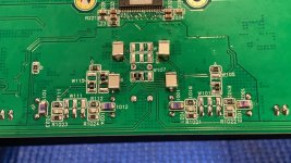
With all the chatting going on about various capacitor modifications to the TPA3255 amplifiers, I had to break out the surgical iron and join in the fun. Not because there is anything needing “fixing”, but because we are Tweakers in search of squeezing out the last drops of performance 😀
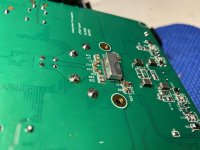
This amplifier uses Silmic II 10uF caps at the input and after the opamps, from past experiences the Silmics are very good as far as electrolytic caps go. I didn’t want to remove them, but added SMD film bypass caps to all eight locations.
For the inputs, I used Cornell Dubilier 1uF FCA Acrylic film caps. This was very easy because the layout has redundant smd pads under the board in addition to the through-hole locations.
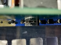
For the post-opamp locations I used Panasonic 0.10uF ECHU PPS Film caps. These are Huge!! They fit perfectly under the board between the Silmic legs.
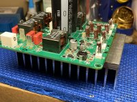
Since I had to remove the heatsink for these mods it was a perfect time to install a new, much beefier heatsink. It’s approximately 3x the size of the “temporary” HS originally installed. To get a little more space between the under mounted smd components and the new HS, I cut and shaped a small 6mm x 12mm aluminum spacer from 1/8” thick plate.
The amplifier has been playing for the past few hours and sounds really good, I will need some more time to get a better feel. I am powering the TPA3255 with a 52vdc linear psu, the new HS made a tremendous improvement with temperature reduction! The HS is 15°C cooler than the previous set up. Even the top mounted inductors are much cooler to the touch.
This amplifier uses Silmic II 10uF caps at the input and after the opamps, from past experiences the Silmics are very good as far as electrolytic caps go. I didn’t want to remove them, but added SMD film bypass caps to all eight locations.
For the inputs, I used Cornell Dubilier 1uF FCA Acrylic film caps. This was very easy because the layout has redundant smd pads under the board in addition to the through-hole locations.
For the post-opamp locations I used Panasonic 0.10uF ECHU PPS Film caps. These are Huge!! They fit perfectly under the board between the Silmic legs.
Since I had to remove the heatsink for these mods it was a perfect time to install a new, much beefier heatsink. It’s approximately 3x the size of the “temporary” HS originally installed. To get a little more space between the under mounted smd components and the new HS, I cut and shaped a small 6mm x 12mm aluminum spacer from 1/8” thick plate.
The amplifier has been playing for the past few hours and sounds really good, I will need some more time to get a better feel. I am powering the TPA3255 with a 52vdc linear psu, the new HS made a tremendous improvement with temperature reduction! The HS is 15°C cooler than the previous set up. Even the top mounted inductors are much cooler to the touch.
Attachments
-
 D93F42E3-7FBA-40E7-9A66-311029F35A14.jpg1,022.3 KB · Views: 429
 -
 47756556-04A5-4A61-BA3C-1C7F43551FBB.jpg764.2 KB · Views: 454
 -
 2E4BF27D-2CC0-4940-BBBA-997AD74FC79E.jpg744.9 KB · Views: 428
 -
 4B4B9035-A4A2-425C-808C-DDB21AC6D777.jpg540.4 KB · Views: 397
 -
 6853BC1B-E1BE-42E6-8C1A-17FA53C4E4E6.jpg1,006.8 KB · Views: 431
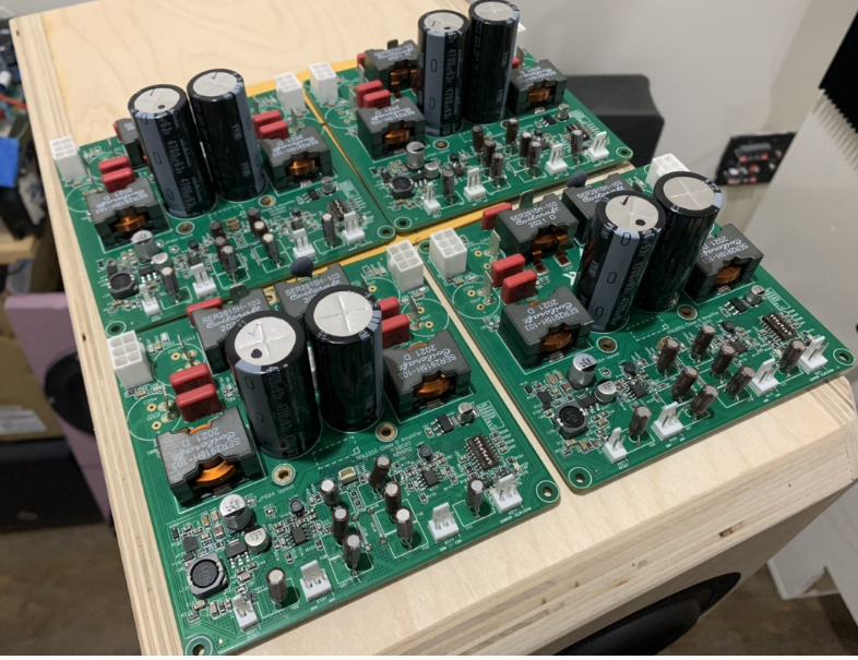
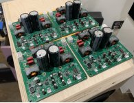
Great news folks. The amps have arrived and I have tested 4 of them so far. They work well and sound great.
Attachments
Last edited:

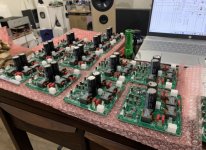
I got 18 amps tested so far. I connect them to a BTSB for balanced in, a 50v smps and speakers. I listen to music on them to ensure they start up AN’s sound good.
Before sending them out, I had to order boxes. They can’t go out in bubble mailers. 🙂

Before sending them out, I had to order boxes. They can’t go out in bubble mailers. 🙂
Attachments
- Home
- Group Buys
- XRK RTR TPA3255 Reference class D Amp GB2