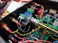
David, why the redundant ground loop breaker when the amp boards already have them?
Nicely organized assembly though !!
Pete
Because it was listed on the Prasi PSU schematic, so I added it.
Is it a problem that it is there?
David.
No, there shouldn’t be. Just as long as all input and output terminals aren’t grounded to case I think you’re good.
Because it was listed on the Prasi PSU schematic, so I added it.
Is it a problem that it is there?
David.
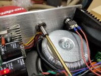
David, three questions about the buzzing transformer (if you’re sure the buzzing is coming from there)….
1. Does it still buzz if you cut power to the amp but turn it right back on (not letting the big caps in the PS discharge)?
2. Does it buzz if the amp sits horizontally (rather than the vertical orientation in the picture)?
3. Do you have the rubber cushions both below and above the tranny, i.e., the tranny sits on a rubber pad and there is a rubber pad below the metal hold down plate on top and you haven’t over tightened the hold-down nut?
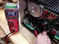
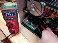
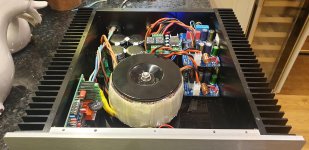
Power supply power up (a good sign), voltages look good.
The Transformer makes a clearly audible buzzing noise for the first 5 seconds of powering on. Is this normal?
David.
David, three questions about the buzzing transformer (if you’re sure the buzzing is coming from there)….
1. Does it still buzz if you cut power to the amp but turn it right back on (not letting the big caps in the PS discharge)?
2. Does it buzz if the amp sits horizontally (rather than the vertical orientation in the picture)?
3. Do you have the rubber cushions both below and above the tranny, i.e., the tranny sits on a rubber pad and there is a rubber pad below the metal hold down plate on top and you haven’t over tightened the hold-down nut?
1. If you cycle it quickly, there is no noise, but if you take a second or two, there is a little noise.
It is only there for 5 seconds when the amp is first turned on.
Now that I think about it my GFA-555II's make a similar sound on power up (just went over and turned them on). I guess with the top off the amp and it being on the bench, it is just more audible
2. Yes.
3. Yes.
Thank you,
David.
The audible buzz is the startup surge required to charge up the bulk caps and magnetize the core of the trafo. Do you have a soft start circuit? A basic CL-60 NTC or 8D-20 NTC in series with your trafo primaries is a cheap soft start circuit. It provides about a 10ohm resistance at cold turn on. Once it heats up in a few seconds, it drops its resistance.
A better soft start is the SFP, also designed by Jhofland. It uses an NTC bit then bypasses it after 2 seconds using a solid state relay. This saves a few watts of power burned off by the NTC.
A better soft start is the SFP, also designed by Jhofland. It uses an NTC bit then bypasses it after 2 seconds using a solid state relay. This saves a few watts of power burned off by the NTC.
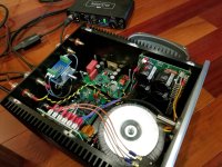
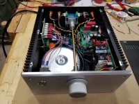
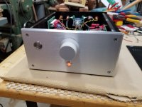
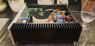
Amp is coming along, last post was with just me testing the power supply, today I connected the speaker protect board and one of the channels.
First test was with a $2.00 speaker to make sure the amp worked, and then with one of the speakers I built.
Works good so far, next up, connected the second channel and wrap it up!
First test was with a $2.00 speaker to make sure the amp worked, and then with one of the speakers I built.
Works good so far, next up, connected the second channel and wrap it up!
Attachments


He’s rounding 3rd and headed for home…..
Nice build DaveFred!
Nice build DaveFred!
Amp is coming along, last post was with just me testing the power supply, today I connected the speaker protect board and one of the channels.
First test was with a $2.00 speaker to make sure the amp worked, and then with one of the speakers I built.
Works good so far, next up, connected the second channel and wrap it up!
These are the last pics, I swear...
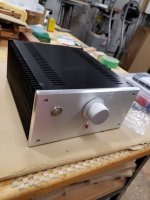
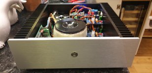
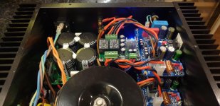
Amp is done!
Some details of how I put it all together in the end,
Alps 10k volume pot was mounted at the rear of the amp near the inputs to make the signal path as short as possible and not cross too many wires.
I tried about 5 different signal wires and found most very difficult to work with.
The signal wire I settled on is Tensility International Corp pn#30-00346, Digikey has it.
The "standard" volume pot extension with bushing is kinda crappy, so I made my own with 6mm brass rod from Amazon along with a 6mm coupler and 6mm linear bearing from Aliexpress.
6mm Linear bearing from Aliexpress
6mm Coupler from Aliexpress
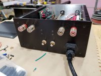
I wanted to have the switch at the front of the amp, but nice switches that are rated properly are hard to come by. I used Schurter Inc pn#1241.6821.1110000 which is rated for 12 amps at 250v.
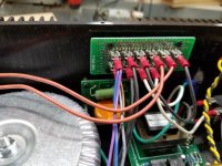
To connect all the powers together I used Bud Industries pn#DMB-4770-CB breadboard which has holes big enough for the faston tabs to fit into. The faston tabs were jumped with a soldered large gauge solid core copper wire on the backside of the breadboard.
The power on lamp was an expensive 110v one, E-Switch pn#PVL14FWS16, but it was dumb dumb easy to install.
All bare stranded wires had a wire ferrule crimped over them before going into screw down blocks.
I think those are most of the little finishing details that I used for "assembling" the amp.
Thanks for everyone's help along the way!
Now for some critical listening,
David.
Amp is done!
Some details of how I put it all together in the end,
Alps 10k volume pot was mounted at the rear of the amp near the inputs to make the signal path as short as possible and not cross too many wires.
I tried about 5 different signal wires and found most very difficult to work with.
The signal wire I settled on is Tensility International Corp pn#30-00346, Digikey has it.
The "standard" volume pot extension with bushing is kinda crappy, so I made my own with 6mm brass rod from Amazon along with a 6mm coupler and 6mm linear bearing from Aliexpress.
6mm Linear bearing from Aliexpress
6mm Coupler from Aliexpress
I wanted to have the switch at the front of the amp, but nice switches that are rated properly are hard to come by. I used Schurter Inc pn#1241.6821.1110000 which is rated for 12 amps at 250v.
To connect all the powers together I used Bud Industries pn#DMB-4770-CB breadboard which has holes big enough for the faston tabs to fit into. The faston tabs were jumped with a soldered large gauge solid core copper wire on the backside of the breadboard.
The power on lamp was an expensive 110v one, E-Switch pn#PVL14FWS16, but it was dumb dumb easy to install.
All bare stranded wires had a wire ferrule crimped over them before going into screw down blocks.
I think those are most of the little finishing details that I used for "assembling" the amp.
Thanks for everyone's help along the way!
Now for some critical listening,
David.
Attachments

I'm confused - you use a linear bearing with rotary motion?
Yes, it's just balls, this one doesn't care if it rotates or slides.
Nice work!
That’s a whole lot of work to connect all those things in a 3D puzzle.
The one reason I like integrated IEC with fuse drawer, rocker switch, and EMI filter. It handles a lot of the grunt work for mains stuff.
That’s a whole lot of work to connect all those things in a 3D puzzle.
The one reason I like integrated IEC with fuse drawer, rocker switch, and EMI filter. It handles a lot of the grunt work for mains stuff.
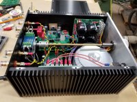
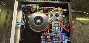
Been off ill this week so far and whilst it has stopped me from doing my usual manual job it has given me time to finish my Xmas amp. Well I say finish it I've pretty much done it all. Boards were populated before hand.
Took me a loooong time as usual. I always seem to have too small a chassis and so packaging and routing becomes tricky. I'm not totally happy with the layout and wire runs but it is what it is for now.
Running a 29v trafo through CRC giving 39vdc.
Using Mark Johnson low voltage soft start thing.
Using some Aliexpress protection board.
Fired up without flames! Offset is about 5mv. Everything seems stable albeit sat idling with no load or input. Only issue I see is the protexr board runs 5v relays and the AC input level is giving the 7805 a hard time. ....I have one I got for class d pbtl so it has 4 relays....un common L and R grounds....runs at 12v. Can I use that?
Anyway hopefully tomorrow i can plug it all in.
Thanks to everyone for the advice in this thread and again to Peter (turion) for the boards he sent me many moons ago before I learnt how to buy my own from JLCPCB!
Attachments
Nice work, Jimk04! Love those thick silicone insulated wires.
You don’t need a PBTL protection board but it doesn’t hurt. It just means the speaker out -ve is isolated from ground.
A lot of people are putting both amps on one side of a chassis even though they have two heatsinks. 🙂
You don’t need a PBTL protection board but it doesn’t hurt. It just means the speaker out -ve is isolated from ground.
A lot of people are putting both amps on one side of a chassis even though they have two heatsinks. 🙂
Got the silicone wire nod from yourself a while back...RC car wires! Good shout.
I realise it is a waste of a sink but for these boards I preffered the signal input wiring to be short so it meant setting the boards out thus.
Hopefully will get to hear it tomorrow.
I've just started reading the Alpha Nirvana thread!��
I realise it is a waste of a sink but for these boards I preffered the signal input wiring to be short so it meant setting the boards out thus.
Hopefully will get to hear it tomorrow.
I've just started reading the Alpha Nirvana thread!��
The Xmas amp pairs really well with the 10F/RS225 Fast speaker that you have. You’ll like it a lot.
- Home
- Amplifiers
- Chip Amps
- Xmas Amp - Dibya's TDA7293 by Jhofland