DougL said:
Someone can probably explain it better, but a "600R:600R" transformer is more of a marketing name than a specification.
Doug
Thanks DougL, I've yet to find someone that can explain it better. Your explanation is very clear and matches our purpose.
Is there any feedback on sonic differences between Edcor, Lundahl, Jensen or other in a DCX or perhaps in a DAC ?
Another interesting question is the turns ratio of the Xformer: I found an original option here :
http://audioprana.free.fr/filtrage_actif.htm
ok, it's french, but you've some pictures and automatic translation should work... just to summarize the main points concerning xformer:
- output of our DACs is very high for our purpose (10V)
- the lower the secondary value, the better
- a xformer with n:1 turns ratio should be used, the output will be V/n. ( here n>1 )
- He tried 600R/3R (I calculated truns ratio = 14:1 !!! ), it can be used but may be obviously not loud enough
- 600R/25R ( I calculated 5:1 turns ratio ) is ok.
It Sounds interesting to me, as I plan to use digital volume before the DCX. But I think it may be usefull for other solutions too.
Any toughts on this?
What are the beneifts and is there any trade-off using 5:1 xformer?
Mic
Hi, I found a comparison between different transformers, including Edcor WSM600, on the sound skulptor web site. The Edcor seem to be the most coloured of the lot.
I've used the Edcor signal transformers ( as well as other custom types) on plenty of DAC outputs.
You can't beat the Edcors for value. They are not the most neutral, but they are often less colored than tube and even some transistor circuits. They do tend to "bloom" a little in the bass, but it's an agreeable sound.
Like most transfos, they tend to make the sound a bit fuller and smoother. A good direction to go with most digital. 🙂
I will probably use them on the outputs of my own DCX 2496.
I don't have enough practical experience to comment.Is there any feedback on sonic differences between Edcor, Lundahl, Jensen or other in a DCX or perhaps in a DAC ?
However, Panoramic's comments are in line with other posters people that have experimented with these transformers. For that Matter, I really hope that a $100 transformer sounds better than a $10 model.
Using a step down transformer is very appealing. However, looking at the DAC chip specifications without the output stage, it appears that the output is only 2Vrms on the differential output. Which would indicate a 1:1 ratio, if we want a 2 Vrms output. If it were 4 Vrms, I would use a 600R:150R (2:1)- output of our DACs is very high for our purpose (10V)
I was hoping for this as well but I found something from Gary Prim that indicated he used 600R:600R.
Just to Be clear, Turns Ratio = Voltage ratio = Resistance ratio (Sq).
You are looking in the right place.
Hope this helps;
Doug
Any new input on these mods?
If anyone is still into transformer outputs on the DCX,
I would appreciate any information on results obtained. Specially on what extra parts are being used besides the transformer.
I am installing 6 x Monacor LTR-110 on the outputs. Also bought parts to "rebuild" the mute function that I do like a lot!! And the 1st order filter just to make sure I don't get high frequencies in my amps. Now is the time to add (or omit for that matter) parts.
Thank you
Peter
Hi Peter, I use transformer outs on my DCX (now retired) and my DEQ. I have a pretty wide selection of 1:1 transformers from Onetics to Cinemag, Jensen, Edcor, Altec, Sowther, some no-name stuff. It all works, but the Onetics (custom) and Cinemag (takes awhile) are my favs. They are large. Jensen may be easier, faster to get. IMO, the 50% nickle cores are the sweet spot.
Usually all you need is a resistor across the secondary to load the transformer and DAC chip with a low impedance load. I find that about 3.3K works well with typical following loads of 20K-50K. If you have the ability to see the waveform on scope, you may be able to tune that a bit, for example with RC instead of just R. Or a combination of both.
At home I have some measurements showing the stock outputs of the DCX and DEQ vs the transformer coupled circuits. The stock Behringer outputs have distortion that rises as the frequency rises. IMD is also much higher than the transformers. I really, really prefer the sound of the transformer outputs to the stock, active circuits.
I hope that helps!
The other possibility is to use a passive RC out from the DCX, then use input transformers on the receiving end. In theory, it's a better solution (as a practical matter, I'm not sure). But no question that input transformers are cheaper and easier to get. I've used 1:1s from Cinemag and Jensen and find very little difference between them.
Hey Pano, if you want to get rid of your retired DCX. let me know. 😀
Hey Pano, if you want to get rid of your retired DCX. let me know. 😀
I use Jensen JT-11-DMPC with really nice results, directly connected to DAC outputs, no RC anywhere. Was able to get all 6 to squeeze inside the chassis. Low distortion even at 20Hz.
Attachments
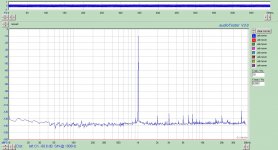
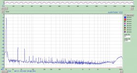
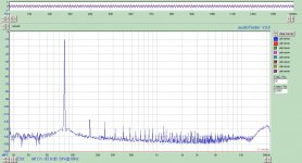
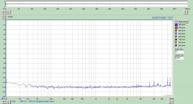
Zigzag, that looks really good. I'm surprised at the low distortion at 20Hz, great result.
SY, I'm keeping the DCX 🙂 It make such a great crossover prototyping tool!
SY, I'm keeping the DCX 🙂 It make such a great crossover prototyping tool!
Revival of the old thread
Thank you all for the information!!
I have build input transformers in my amp to go from XLR to SE and step down 1:0,5. Sounds good though the output from the DCX is still way to high.
I am planning to do the same in my DCX meaning stepping up 0,5:1. That would mean transformers at both ends. Double is not wise I guess if you don't use long cables in an interference rich surrounding. It would double distortion / coloration etc.
Best would be to go 1:1 in the amp and find the simplest solution in the dcx saving space to build both the mute circuit Jan Didden style and maybe an opto-coupled (LDR) volume control too.
Anyhow I am using prototyping boards in my DCX in order to experiment the different solutions. Since I have no scope I would like to know what I could test on those transformers with an ordinary multi-meter besides my (I hope still extraordinary) ears.
Unfortunately unable to shrink the spec-sheet of the Monacor LTR 110 transformers I use 😱
Thanks again
Peter
Take a link
😉 to there:
http://www.monacor-spain.net/Manuales/LTR110.pdf
Hope this helps
Greez
Sigfire
😉 to there:
http://www.monacor-spain.net/Manuales/LTR110.pdf
Hope this helps
Greez
Sigfire
Thanks for the link.
If you come straight out of the DAC chips on the DCX board into the primary of the transfo, that's all you need. Level will be a little low, like 1.6V RMS, so you can use a step up transformer is you wish. Put anything from about 3K-6K across the secondary. It won't hurt to not put a resistor there, it's just better practice to load the circuit a bit.
I have found no need for a any downstream mute circuit with my DCX. No pops, no clicks, no noise. The software mute (the buttons) still works. The DEQ does pop some and might need a mute circuit.
Agreed, no pops or clicks with xfmr output, and the mute works.
I load the circuit at the amplifier input with 2-10k resistors to ground, since the xfmr does not have a center tapped secondary. I like to put burden at the load rather than at the source.
Be careful about the resistive and capacitive load you use when going step-up. 1:2 step-up results in x4 burden.
That's true and thanks for mentioning it, I should have.  If you use a step up, the DAC chip effectively sees a lower impedance. Use higher value resistors in this case. AKM spec these for a >600 ohm load. In some of their spec sheets they show 630R on each leg to ground (after DC blocking). I don't think you have to load it that much.
Also agree on putting the load and the transformer at the amp, if you can. My source and amp are so close it really doesn't matter (for me).
If you use a step up, the DAC chip effectively sees a lower impedance. Use higher value resistors in this case. AKM spec these for a >600 ohm load. In some of their spec sheets they show 630R on each leg to ground (after DC blocking). I don't think you have to load it that much.Also agree on putting the load and the transformer at the amp, if you can. My source and amp are so close it really doesn't matter (for me).
how to measure needed impedance?
All,
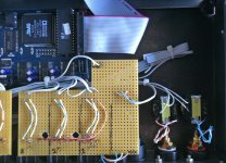
I am listening to a very nice sounding setup now. DAC outputs directly to the XLR plugs and the xformers in the amp. The only "but" is the still quite high output (even when using 1:2,5 step doen x-formers in the amp)
I have left ample space to place an impedance correction circuit to load the dac and attenuate before the XLR plugs. Unfortunately I don't know how to measure the impedance needed to do so. Even don't know if this can be done with a normal multimeter.
Alternatively I could build this circuit in the amp too (not my 1st choice). Still need to know how to measure though 😕
All,
I am listening to a very nice sounding setup now. DAC outputs directly to the XLR plugs and the xformers in the amp. The only "but" is the still quite high output (even when using 1:2,5 step doen x-formers in the amp)
I have left ample space to place an impedance correction circuit to load the dac and attenuate before the XLR plugs. Unfortunately I don't know how to measure the impedance needed to do so. Even don't know if this can be done with a normal multimeter.
Alternatively I could build this circuit in the amp too (not my 1st choice). Still need to know how to measure though 😕
Attachments
Last edited:
Just put 5K or 10K across the secondaries and you'll be fine.
I don't really understand your high level, unless you amp has a lot of gain. Is it a power amp without a volume knob?
I don't really understand your high level, unless you amp has a lot of gain. Is it a power amp without a volume knob?
If you are measuring directly after the output of the DAC, then the RMS voltage should only be about 1.75 volts. Your amplifiers should be okay with this. It is not clear why you need to step the voltage down. Are you confident about what or where you measured?
- Status
- Not open for further replies.
- Home
- Source & Line
- Digital Line Level
- XFormer for DCX 2496 output ONLY