now just build it

(besides SE bias value , it seems that catch is in xconductance difference between amplifying diagonals)
(besides SE bias value , it seems that catch is in xconductance difference between amplifying diagonals)
Hi again,
I think I found the secret of good sounding XA line.
So look at the first simulation - "symmetrical" asymmetric 4/5; 5/4 MOSFETS like XA30.8 at 1W on 8ohm output with no CCS at all - dominant 2nd harmonic. On the next pictures until 5th simulation you can see the same circuit with increasing CCS current. As you can see 3rd harmonic is totaly independent of CCS (depends only of global/local feedback) but a miracle is of 2nd one. At 413 mA per branch 2nd harmonic is getting strictly parallel to 3rd by a distance of about 8dB. This distance is reducing along with the increase in the output power, but stays parallel.
So, can we increase/decrease distance between the harmonics? The answer is yes !!! Look at simulation 6th & 7th. I've throw away next MOSFETS so we get "symmetrical" asymmetric 3/5; 5/3 MOSFETS at the same output conditions as above. 6th without CCS - as previously dominant 2nd harmonic but at 7th throwing away MOSFETS & increasing the CCS current by factor of 2 leads again to parallel 2nd & 3rd harmonic with distance between them of about 13dB !!! Moreover this parallelism is preserved with increasing in the power output - sim. 8th. Think, this little amplifier can work at 10W like SE !!!
Conclusions:
1. 3rd harmonic only depends of bandwith / feedback balance,
2. 2nd harmonic is dependent of deep of "symmetrical" asymmetry, higher asymmetry in N/P channel MOSFETS leads to bigger 2nd harmonic (adwerse effect is bigger THD of course)
3. CCS can modulate parallelism of 2nd & 3rd harmonics. Decreasing MOSFET count, needs same increasing of Iccs. So missing one MOSFET per branch I=Iccs, missing two -> I=2xIccs, three I=3xIccs etc. Throwing away all lower/upper MOSFETS in the branch and relatively multiplying Iccs leads to Xs amplifier?
4. Getting 2nd & 3rd harmonics parallel probably leads to proportional delay of frequencies and maybe this is the miracle of good sounding amplifiers.
Uff, so should I get a Nobel price? Is it patended?
The saddest thing, is that I've never heard original XA... amplifier 🙁🙁🙁
The only one that might be audible at 1W is no CCS 3/5 5/3.
Is the goal to hear 2nd Harmonic at 1W?
I don't think you can get a prize for this. Nelson has been sharing similar tweeks with us for a while.
Last edited:
At higher power levels, you may wish for greater cancellation of 2nd. Also, to what degree does phase play into the mix?
XA30.8 is 4/5;5/4 because it is - pictures don't lie. Other configurations are answer on question how can we shape 2nd i 3rd harmonic. You can get higher level, lower level, faster growing or slower growing characteristic of 2nd and you know how to do it. The 3rd is not configurable & depends mainly of quality of parts used in circuit, and then of total feedback. But if you can shape 2nd, you can relatively change volume of 3rd too. You can lower both the 2nd & 3rd by increasing feedback, delaying response then get higher TIM and awful amplifier.The only one that might be audible at 1W is no CCS 3/5 5/3.
And up to about 30% of total power. It isn't a solution for XA.8?Is the goal to hear 2nd Harmonic at 1W?
I think you are heading in the right direction but I think you need to do some listening tests to work out what quantity of second harmonic is pleasing to your ears with your speakers and music.
In my opinion any low order harmonic that is below 80dB will be inaudible. That's what you need to work out. I can't tell you what ratio sounds best except I love ACA and that amp has relatively high levels but I don't listen to classical music.
In my opinion any low order harmonic that is below 80dB will be inaudible. That's what you need to work out. I can't tell you what ratio sounds best except I love ACA and that amp has relatively high levels but I don't listen to classical music.
Last edited:
At higher power levels, you may wish for greater cancellation of 2nd. Also, to what degree does phase play into the mix?
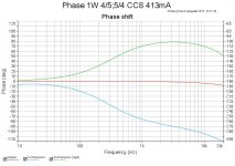
I think that phase shifts plays dominant role in localisation and resolution of sound sources - from psychoacustic - ears are more sensible to phase shifts then to volume & frequency. Here comes some simulations:
1. 4/5;5/4 1W CCS 413 mA
2. 4/5;5/4 10W CCS 413 mA
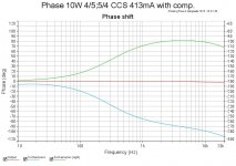
3. 4/5;5/4 10W CCS 413 mA with compensation
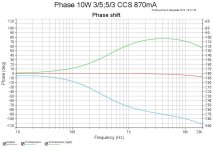
4. 3/5;5/3 10W CCS 870 mA
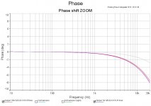
5. Zoom on total phase shift (the grey is one with compensation (3)).
First, second and fourth are about the same, power and MOSFET configuration have not influence on phase shift - 8deg - good. After compensation (3) phase shift = 3dB - much better. This kind of compensation has not influence on harmonic level and shape at lower frequencies.
So it's time to build something.
Attachments

Simulations with lower CCS
Just for You.
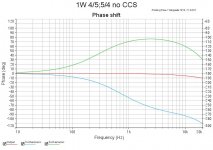
1. 4/5;5/4 1W no CCS
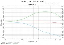
2. 4/5;5/4 1W CCS 133 mA
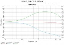
3. 4/5;5/4 1W CCS 275 mA
Generally nothing special.
Run again with lowered CCS value
Just for You.
1. 4/5;5/4 1W no CCS
2. 4/5;5/4 1W CCS 133 mA
3. 4/5;5/4 1W CCS 275 mA
Generally nothing special.
Attachments
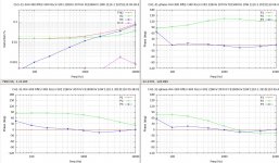
Here are some actual measurements of an amplifier I built which is similar to the XA30.8. The frequency sweeps are at 10Watts into an 8 Ohm load as follows:
DiffOut harmonic Levels vs. Freq | -phase Out Harmonic Phases vs. Freq
DiffOut harmonic Phases vs. Freq | +phase Out Harmonic Phases vs. Freq
DiffOut harmonic Levels vs. Freq | -phase Out Harmonic Phases vs. Freq
DiffOut harmonic Phases vs. Freq | +phase Out Harmonic Phases vs. Freq
Attachments
I need to clarify two points about the plots in my previous post.
The H1 (fundamental) phase plots are totally flat because my distortion analysis software does not have access to the input to the amplifier. The H2 and H3 phases are relative to H1 of the output.
The H3 phase information at 50Hz is not to be trusted since the H3 magnitude is near the noise level of the system.
Hi again,
I think I found the secret of good sounding XA line.
So look at the first simulation - "symmetrical" asymmetric 4/5; 5/4 MOSFETS like XA30.8 at 1W on 8ohm output with no CCS at all - dominant 2nd harmonic. On the next pictures until 5th simulation you can see the same circuit with increasing CCS current. As you can see 3rd harmonic is totaly independent of CCS (depends only of global/local feedback) but a miracle is of 2nd one. At 413 mA per branch 2nd harmonic is getting strictly parallel to 3rd by a distance of about 8dB. This distance is reducing along with the increase in the output power, but stays parallel.
So, can we increase/decrease distance between the harmonics? The answer is yes !!! Look at simulation 6th & 7th. I've throw away next MOSFETS so we get "symmetrical" asymmetric 3/5; 5/3 MOSFETS at the same output conditions as above. 6th without CCS - as previously dominant 2nd harmonic but at 7th throwing away MOSFETS & increasing the CCS current by factor of 2 leads again to parallel 2nd & 3rd harmonic with distance between them of about 13dB !!! Moreover this parallelism is preserved with increasing in the power output - sim. 8th. Think, this little amplifier can work at 10W like SE !!!
Conclusions:
1. 3rd harmonic only depends of bandwith / feedback balance,
2. 2nd harmonic is dependent of deep of "symmetrical" asymmetry, higher asymmetry in N/P channel MOSFETS leads to bigger 2nd harmonic (adwerse effect is bigger THD of course)
3. CCS can modulate parallelism of 2nd & 3rd harmonics. Decreasing MOSFET count, needs same increasing of Iccs. So missing one MOSFET per branch I=Iccs, missing two -> I=2xIccs, three I=3xIccs etc. Throwing away all lower/upper MOSFETS in the branch and relatively multiplying Iccs leads to Xs amplifier?
4. Getting 2nd & 3rd harmonics parallel probably leads to proportional delay of frequencies and maybe this is the miracle of good sounding amplifiers.
Uff, so should I get a Nobel price? Is it patended?
The saddest thing, is that I've never heard original XA... amplifier 🙁🙁🙁
If you live not far from Wroclaw I can present the amplifiers on my system. I got now the XA 60.8 and a Aleph X 60w (pm me if you're interested)
Can please someone tell me if the 160.5 are still available? Special order?
I am trying to build a CCS for a mosfet testing circuit but I find the current sources discussed for the XA30.8 to have too much drift with temperature. (For example: post #235 http://www.diyaudio.com/forums/pass...gle-ended-current-sources-24.html#post4212439). Both the ZTX450 (or 550) and the IRFP240 have significant tempco issues that do not tend to cancel one another. What I need is an adjustable constant current source for the range 100mA to 1.5A. The adjust can be accomplished either with a pot or by changing the (high current) current sense resistor. Perhaps a thermistor could be added to one of the circuits of post #235 to improve the temperature stability. Any suggestions?
I am trying to build a CCS for a mosfet testing circuit but I find the current sources discussed for the XA30.8 to have too much drift with temperature. (For example: post #235 http://www.diyaudio.com/forums/pass...gle-ended-current-sources-24.html#post4212439). Both the ZTX450 (or 550) and the IRFP240 have significant tempco issues that do not tend to cancel one another. What I need is an adjustable constant current source for the range 100mA to 1.5A. The adjust can be accomplished either with a pot or by changing the (high current) current sense resistor. Perhaps a thermistor could be added to one of the circuits of post #235 to improve the temperature stability. Any suggestions?
Hello lhquam.
May consider using LM317 which is a variable positive voltage regulator. It has 3 pins, Vin, Vo, and Vadjust. The voltage difference between Vo and Vadjust is + 1.25 Volts. Connect a resistor [Rsense; variable or fixed] between Vo and Vadjust and thus get Io = 1.25V/ Rsense. Minimum Rsense = 0.8 Ohms, an minimum Vin-Vo ~ 5Vdc.
The above is like the far right circuit in your schematic.
Antoinel: The LM317 by itself has neither the necessary power dissipation (> 30W) nor the current capabilities (up to 1.5A). Perhaps an LM317 along with an IRFP240 (and necessary resistors and ?) might work.
I found this IXYS app note: http://www.ixys.com/documents/appnotes/ixan0063.pdf. See figure 3.
Thanks lhquam for the above informative link. A typical current booster using LM317 is in its data sheet as such. A resistor in series with its Vin port generates the bias/drive [Vbe] for a BJT power Darlington. The collector of BJT is tied to Vo of LM317. A P channel Mosfet may well be used instead of BJT.
The thermal/current protection circuitry in LM317 are valuable.
I am trying to build a CCS for a mosfet testing circuit but I find the current sources discussed for the XA30.8 to have too much drift with temperature
I often use an optoisolator for the control, as the LED as sensor has a sharp
knee and is relatively temperature insensitive. It drops about 1.1v, which
allows for some generous degeneration on the Fet, and can give a decently
high impedance.
😎
I often use an optoisolator for the control, as the LED as sensor has a sharp
knee and is relatively temperature insensitive. It drops about 1.1v, which
allows for some generous degeneration on the Fet, and can give a decently
high impedance.
😎
Firsure 5 of the TI datasheet http://www.ti.com/lit/gpn/4n35 for the 4N35 suggests that the LED forward voltage at a few mA might change by about 0.06V-0.1V between 25C and 70C. Were you using a different part, or am I looking at the wrong curves on the datasheet?
I am trying to build a CCS for a mosfet testing circuit but I find the current sources discussed for the XA30.8 to have too much drift with temperature. (For example: post #235 http://www.diyaudio.com/forums/pass...gle-ended-current-sources-24.html#post4212439). Both the ZTX450 (or 550) and the IRFP240 have significant tempco issues that do not tend to cancel one another. What I need is an adjustable constant current source for the range 100mA to 1.5A. The adjust can be accomplished either with a pot or by changing the (high current) current sense resistor. Perhaps a thermistor could be added to one of the circuits of post #235 to improve the temperature stability. Any suggestions?
The less intelligent approach would be to use lateral mosfets. Tempco is near zero and above 500mA they tend to conduct slightly less current with increasing temperature which is the opposite of a bucket load more current with increasing temperature for the vfets.
Other wise the optocoupler works very well indeed. Thanks to Papa.
Last edited:
After doing more analysis, the CCS temperature drift is due to the ZTX450 and not the IRFP240. The BJT transistor is being used as a low gain differential amplifier of the voltage across the current sense resistor. Thermal drift in the Vgs of the mosfet doesn't really matter. It the BJT is sufficiently isolated from the heatsink of the mosfet, then its thermal drift should not be a major issue. In retrospect, the thermal drift issues of my mosfet measuring setup appear due to be the device under test rather then the CCS. I will eventually elaborate on this in a new thread.
- Status
- Not open for further replies.
- Home
- Amplifiers
- Pass Labs
- XA.8 single-ended current sources