No. they don't. I just end up using them for a lot of projects. I bought 250 a while back and have gone through about half of them. I got the 300 recently because they were dirt cheap, the same as pass amps (not a significant reason) and I am sure I will go through them eventually.I have the same amp. Do these resistors go bad after some time & exposure to temperature ? recently replaced all the power caps but nothing else
If you have a source resistor go bad, something else is likely cooked. These X amps are super tough though. They generally just don't ever break... Like ever...
Hello,
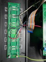
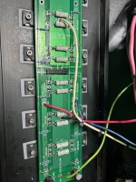
I have a PASS Labs x150.50 amplifier (S/N 14695) I think it is the first version (the board ID is X150.5R0 - PASS LABS 2003) I had to change the output connectors and now I don't remember how the cables should be connected to the output connectors .
Can anyone help me? Maybe if you have the same amplifier as mine you can post some pictures of the connections.
Thanks.
Attachments

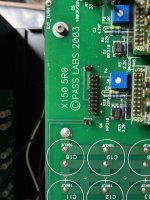
Reference these markings and look on the output stage to see if they are there as well. I suspect they stand for the + phase and - Phase. Probably the gate resistor traces since there are two on each phase. Probably +P +N & -P -N


Looks like the two -'s are for N-type mosfets and + are for P-type mosfets. I would wait for the mighty Zen Mod to chime in or call Pass Labs if needed. You can put some markings on the PCBs to indicate the direction for the future.
Unrelated question for the mosfet vs TL431 + thermistor on the bias circuit. Is there an advantage of one over the other?
Unrelated question for the mosfet vs TL431 + thermistor on the bias circuit. Is there an advantage of one over the other?
I don't have a copy of this art, so you are best off sending the image to kent@passlabs.com
so that he can check on it.
so that he can check on it.
An easy way to make sure it is correct is with a meter. The IRF210 wide tab/pin on main board will connect to the IRF240 gates on the output board. There is 220 Ohms from that point to the gates or 0 Ohms where all the ends of the 220 Ohm resistors join.
I checked the layout on this and the two + + sides on the main board connect to the side with the red power wire.
This will also Ohm out correctly. Half of each module feeds the left and half the right.
This will also Ohm out correctly. Half of each module feeds the left and half the right.
So, I replaced all electrolytics in the front end. I spent several hours balancing the offset and
bias to 140mv. Zm. your limit. To me. It is the most beautiful sound In the world as I know it. I am soon to be in possession of a x 2.5. The Pass Labs John Dunlavy thing is beyond cool It is sublime. Phase and time coherence. Cest Tou.
bias to 140mv. Zm. your limit. To me. It is the most beautiful sound In the world as I know it. I am soon to be in possession of a x 2.5. The Pass Labs John Dunlavy thing is beyond cool It is sublime. Phase and time coherence. Cest Tou.

I replaced all the PS caps last year in my x150.5 , from memory there are very few small caps in the front end board which I replaced as well. Did not yield any improvementsSo, I replaced all electrolytics in the front end. I spent several hours balancing the offset and
bias to 140mv. Zm. your limit. To me. It is the most beautiful sound In the world as I know it. I am soon to be in possession of a x 2.5. The Pass Labs John Dunlavy thing is beyond cool It is sublime. Phase and time coherence. Cest Tou.
I just replaced the small guys. I also turned up the bias and spent a lot of time balancing before I listened. Really have no clue about if the small electrolytes affect sound, but the biasing exercise was incredibly fruitful.I replaced all the PS caps last year in my x150.5 , from memory there are very few small caps in the front end board which I replaced as well. Did not yield any improvements
X150.5 is singing so wonderfully sometimes I have to pinch myself. It remains a reference for all other changes to source... In the cooler temperatures, it is serving double duty as a heater in the front room and after 3 hrs listening, the needle is dead still at about 3/5 till center. Temp ever so slightly approaching 50. At 50, the best recordings will come to play..just heaven. As always reference speakers are phase and time coherent Dunlavy Audi Labs. PS, that's the ZenMod Iron Pre SUSY right below. A thing of beauty that. Brought to another level with a shunt attenuator with zfoil load and takman to ground. On the X150.
5 I'm thinking about shifting this reference amplifier (reference is all relative mind you) by removing the DC blocker and replacing the input signal resistors with zfoil. Zfoils have made an audible difference in my iron pre and my hafler (Jfet cascode transnova variety) amp systems. My question is does the X150.5 circuit have an input shunt before and after the DC blocker? And what would be the approximate equivalent. Or better yet direct me to the literature that I can read to allow me to solve this on my own. I can also probe and reverse engineer easily enough, but that would require taking her out of service for a short spell..Peace


5 I'm thinking about shifting this reference amplifier (reference is all relative mind you) by removing the DC blocker and replacing the input signal resistors with zfoil. Zfoils have made an audible difference in my iron pre and my hafler (Jfet cascode transnova variety) amp systems. My question is does the X150.5 circuit have an input shunt before and after the DC blocker? And what would be the approximate equivalent. Or better yet direct me to the literature that I can read to allow me to solve this on my own. I can also probe and reverse engineer easily enough, but that would require taking her out of service for a short spell..Peace
I have bypassed the DC blocking caps on the .5 series before. The circuit behaved. You can also play with different caps in that position. There are also a few other tweaks you can play with on that circuit. All fun things. Just keep in mind the stock settings and you will be good.
That's some good data on the blockers. I'm pretty sure the input impedance is a 100R load and 100k to ground shunt. Which is 100k input impedance .And resistance of the DC cap is negligible..I'm just going to order 100R and 100k Zfoils and short the blockers. I might have to learn how to dial in a bit more 2nd order if the detail and and 3 dimensional soundstage becomes, well, beyond what I experience, because man, I really can't image anything more. .... The Cordell 230c has shunts before and after DC blocker, so I was spinning a bit on that.. working on some of those boards for monoblocks with 5 pairs of factory matched exicon lateral mosfets. PS curious about "other" tweaks and have you soldered any Zfoils? For me Vishay VAR thin foil placed in the signal path have been low hanging fruit yielding fidelity I never imagined in my wildest dreams. Uncanny really. Cheers
- Home
- Amplifiers
- Pass Labs
- X150.5 testing and planning for the future