I recently acquired a nice X150.5 and of course the first thing I did was popped the hood. Man, what a beautiful layout and build quality! This is a 2011 build date and I don't have much use history. It sounds beautiful with my Dunlavy SM-1's and I measured 45deg. C. heatsinks after a few hours. I plan to test the voltage drop across each of the output resistors (0R47) to test how matched the output sections are. Looks like 4 sections of 5 pairs per bias quadrant. My questions relating to testing, preventative maintenance and planning for the future are as follows; 1. should each of the measurements only have to match each other within the quadrant or should they match for the entire channel? Seems like that could be the reason for 4 bias pots... 2. I have read MOX resistors have a less reliable duty cycle and wonder if replacing the Panasonic ERX would be prudent? I could not find a life expectancy on the datasheet... I see Digi key has a reasonable supply of the ERX 0R47 and 3.3K type S 3w in stock so to plan for the future, I'm going to buy 100 of each unless otherwise advised. 3. Why is 50deg C is the optimal operating temp for SQ? when I measure Vgs for a new IRFP240 at room temp. I get about 3.15 V, then after sitting on the radiator, 3.0 V. Is the mosfet quieter at 50deg C or does the resistor TC curve come into play? 4. Should the needle on the bias current meter be vertical and sitting on the circle ? And lastly, when the PSU caps give up their life, 25 mm 40v caps seem to be un-obtainium... and I didn't see any R between and of the C's... I'm not opposed to re-imagining that PSU pcb if for no other purpose than to fit 30mm caps.
Peace

Peace

quadrants are matched groups, but you need to see similar Iq figures (voltage across 0R47) for each/every mosfet in all quadrants
if you have 25C above ambient on top of heatsink you're good
shoot for 50C to 55C at top of heatsink in summer
then, measure relative and absolute offsets
if speakers see less than 100mV and outputs are up to 500mV from GND potential, that's it
then ......... just chill
this could be helpful: https://www.zenmod.in.rs/pass-labs-x150-5-checkingadjusting-offsets-iq-and-gain/
I wonder if you should consider reflowing some solder on the big R's. Looks like a void on the left one, though it may look fine on the other side. It's hard to see well, though.
Yes, I noticed that in the photo as well. Could be a shadow, but I'll definitely give it a closer inspection!
Thanks ZM. Very helpful. I think I figured out the temp variable. It seems it is just the temp at which the circuit is designed to keep the fet on (Class A bias) based on Vgs Tc and the power/heat dissipation capabilities of the heatsink ?
temp is, even if "just" resulting fact, perfect criteria for setting Iq
simply because entire system is physically constructed with final temperature as one of defining factors
something as - there was intended dissipation figure from very start, and case is devised taking in account physical volume to accommodate necessary hardware and then to forward produced heat in ambient
same as one of Boyz making some Papamp, and asking beforehand which Modushop case to buy and how big Donuts and how many cap cans ..... and then some of other Boyz is just pointing him on appropriate photo serial and some text
I wonder if you should consider reflowing some solder on the big R's. Looks like a void on the left one, though it may look fine on the other side. It's hard to see well, though.
It's not necessary or advisable to solder both sides of the board, just the side having traces from the pad.
If the pad in question is not soldered on the plane side then it should be, to provide a direct path
for the current rather than through the via.
for the current rather than through the via.
I don't think they intentionally soldered it only on one side. Likely fully soldered on the other side which is really good enough for production work. Also, that is the side they were looking at when soldering. The pad conducts to both sides... That is the output plane which they may have put on both sides to double up the amount of copper the output sees. Or just the pad.
Could fill solder on the top if your OCD is kicking in. If you are goind to flow some resistors, make sure you have a good soldering gun. Cardas solder flows like butter. Isopropyl alcohol is good for cleaning the leftover flux off.
.47 is a popular value for Pass Labs/Firstwatt/Pass DIY designs. I bought 250 of them from I believe Digikey and have been very happy with that decision so far. The "M" on the resistors in the pictures stands for Panasonic I believe. I thought that Pass used the ERX resistors on their designs. Those may already be ERX. I wouldn't bother replacing them though unless needed.
Going off of memory from what I read, 50 degrees celcius is the maximum bias that Pass thinks is reasonable to put out into the world and not expect issues to arrise. I believe he runs his amps hotter but he is the designer so he can get away with that.
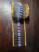
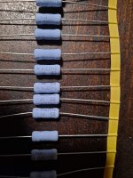
Interesting I did not know that. Do they make them for Panasonic? Here are a couple pictures of the ERX resistors I got from Digi key
in short, Technics, Panasonic, National ........ everything is/was Matsushita
I mean, interesting when chasing parts and facts
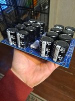
I remember some years ago someone wrote that the caps in the J2 power supply was 'nameless' even after others pointed out the meaning of the "M". 🙂

OT alert:Also hear some Panasonic caps that also have The same "M"
That power supply looks great, but is that an animal crate, screen door, or jail in the background?
Made me think of this scene:
- Home
- Amplifiers
- Pass Labs
- X150.5 testing and planning for the future