This weekend I had a chance to listen to a nice 2x15" open baffle, that had a large curved front horn and a conical extension on the back. It sounded great and looked very cool. Therefore I would like to put together a test baffle inspired by it.

It would be really easy to build. What I do not like on a H frame are the parallel walls, here, only the top/bottom (not shown) would be parallel.
My question is, would this work? Would the baffle width be counted including both sides of the wings or would the bass frequencies ignore the inner triangle and just bend to the back?

I did some experiments on exactly this configuration, with the width of each wing about half of the center panel width but without a top. The X-wing was not any more helpful compared to just making the planar baffle a few inches wider.
This configuration is probably not as helpful as a true H-frame although I have not made any direct comparisons. If you are going to use a decent size driver (e.g. 15 or 18") then the total width including the wings starts getting pretty large and it will be physically and visually big in the listening space.
This configuration is probably not as helpful as a true H-frame although I have not made any direct comparisons. If you are going to use a decent size driver (e.g. 15 or 18") then the total width including the wings starts getting pretty large and it will be physically and visually big in the listening space.
Great idea! You could use hinges to be able for flexible opening angle. The back wings could be made shorter imo. Just think about to prevent the acoustic short at the top.
Dipole peak is defined by shortest distance from driver cone front to cone back, so if over the top panel distance is shorter than over side wings, it is no sense to make large side wings, only if you want to have some form of horn in higher frequencies. Most economic way of getting symmetrical frame is H-frame. I had this kind of H-frame woofers with 2x12" drivers and I had not measured any problems from parallel walls, if they exist then in very small amplitudes.
Just an extreme example of a similar construction:
http://vinylsavor.blogspot.com/2014/05/high-end-2014-room.html ;-)
http://vinylsavor.blogspot.com/2014/05/high-end-2014-room.html ;-)
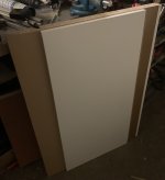
This first idea is based on 800 x 400 mm panels (that are sold in hobbymarkets), all the same dimensions. The top is not shown, for the first test, it would be just rectangular, if it is ever built properly, it will be in the shape of an hour glass.
The top panel length would be ca 57 cm and front width ca 97 cm with 45 degree angles - which would be about the biggest I could possibly fit into the room. It is meant for two 15" woofers.
I did some Hornresp simulations and the X configuration seems to be slightly flatter with better high end extension.
Hinges are a good idea, so that I can try H, X and Y or even Delta shapes if there is any interesting difference. And it will be even easier to build, too.
The center part will be cut out of 38 mm thick kitchen work top, woofers mounted from the front with a recess. The wings will be 16 mm thick shelves on 600 long mm piano hinges. I need to visit the local hobby market this week🙂
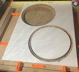
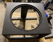
Finally a free evening to make a few cuts outside. I have decided to make the central part slightly wider, the woofers will be slightly offset to the sides. The plan for the weekend is to CNC the woofer openings and mount everything together - and maybe first music test as well.
Attachments
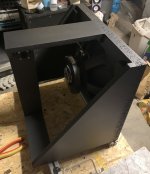
The baffle is cut. Tomorrow, I will sand the edges and paint them black, so that the chipboard holds better together. I had a small incident with a blunt milling bit - I will just leave the mark there, it is just a test unit anyway.
Attachments
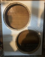
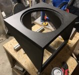
Threaded inserts are installed. The paint on the edges served its purpose, just added a second layer on the outer edges and around the inserts, where I had to file down the bulges caused by them. If I can find the right size of screws, the wings will be installed in the afternoon.
I have a question - do I need an air tight seal on the hinges? I would think it is not necessary, since it is open baffle and the wavelengths are very long.
I have a question - do I need an air tight seal on the hinges? I would think it is not necessary, since it is open baffle and the wavelengths are very long.
Attachments
Not sure what your goals are here so it’s hard to get on board with your X wing. You’re creating different directivity patterns than intended by the design…..to produce a cardioid response in the bass and lower bass region to eliminate room modes and resonance.…..what you’ll wind up with here is room excitation……you could have done that with a single driver in a box and save the wood, time and floor space.
It’s important to recognize that the ideal reproduction of sound in a closed space is as close to a point source as you can achieve and wide baffles destroy that presentation…..they’re a compromise in every sense of the word because they create boundary gain….or a gain in amplitude created by the reflection of sound across the extended surface.…..and your ears are designed to recognize or identify this as a boundary in a 3D space……not a good thing. The ideal ‘point source’ has even power response in a 3D space, equating to a close to as ‘baffle less’ presentation of the driver as possible.
For one of the best examples of a more modern understanding of the point source, look towards the work of Linkwitz labs and notice how those designs became progressively narrower or smaller, allowing the system to NOT draw attention to itself or its presentation through the illumination of boundaries. Notice what’s happening over at B&W where they’re baffles are getting narrower and they’re scattering surface reflections with abrupt flanges around the drivers as their research is drawing them to the same conclusion. Over at Sonus Faber, they re introduced the wide baffle Stradivari…..only to have it trounced by the Homage by listeners impressions at high end shows around the globe.
Now if you were going to create a HUGE continuous boundary or ‘baffle wall’…….well….that’s a different story where the point source and the 3D boundary layer are one….sans the floor and ceiling of course…..but the effect is the same and profound. In this instance, the rear wave is completely isolated and the time domain becomes accurate by eliminating half of the power response anomalies in the process. But your design doesn’t do either…..it just calls attention to more 3D boundaries in the nearfield and presents an artificial yet non beneficial power response.
It’s interesting how the simulations from HornResp are being interpreted in a lot of DIY designs these days, completely disregarding the purpose of horn loading through compression, but instead adopting this ‘pseudo science’ of a waveguide effect.…..try not to stay at that summer camp.
Last edited:
The intention here is to use as an OB subwoofer/bass unit with equalization. Absolutely maximum upper frequency would be 200 Hz, most probably even less. And it will serve as a stand for a large MEH.
I have 4 pieces of SB 15OB350 woofers, this is just the first experiment. And I am definitely open to suggestions for a different enclosure style. So what you would suggest is a narrow baffle or an H-frame? Maybe I should start a thread on how to use the woofers in the best way.
I have 4 pieces of SB 15OB350 woofers, this is just the first experiment. And I am definitely open to suggestions for a different enclosure style. So what you would suggest is a narrow baffle or an H-frame? Maybe I should start a thread on how to use the woofers in the best way.
Thanks for clarifying……there’s a lot of folks doing dual 15’s with one bass unit and those other wonky Lii type fullrange above….yuuuuuuck
H frame or W…..either will do and preserve floor space. The W is obviously more complex to build….what I like about em is neither wave front is ever on axis so if the woofers have extreme breakup modes higher up, you can use a shallower crossover and not have to worry about any of that effecting the on axis response of the system overall.
I use 18’s to 200hz…..they’re actually crossed at 80hz with a 2nd order low pass.
Best additional advice I can add is to make sure there’s no panel resonances or excitation. While there’s no box resonance capacity, bass tends to drone in complex harmonic content and with enough of it, it doesn’t take too much to get a side panel excited and singing along with the music. Once complete, give it the ol tap test and make sure those sounds are outside of the passband. Woofer baffle panels would be fine with 3/4” material surface mounted, but for the sides I’d go double that along with the top and bottom.
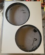
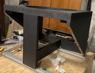
In the end, the X-Wing looks more like a Tie Fighter🙂


There will be a large wooden plate placed on the top for measurements. I have to mow the lawn now, but hope for nice weather tomorrow to install the drivers and measure. I am especially interested if I will be able to measure some resonance frequency shift and difference s between 0, 45 and 90 degrees.
There will be a large wooden plate placed on the top for measurements. I have to mow the lawn now, but hope for nice weather tomorrow to install the drivers and measure. I am especially interested if I will be able to measure some resonance frequency shift and difference s between 0, 45 and 90 degrees.
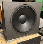
Drivers are installed, but it is getting too cold and damp for outdoor measurements. I also need to figure out a way how to move this thing more easily, it became quite heavy now and the nice 3D handles I printed do not allow full unfolding (I should have realized that sooner).
There is no way this could fit my smaller listening room, so I came up with this - a small open baffle bass module that fits the shelf. The baffle is identical to the DSP assisted BR box I built a few weeks ago. Inspired by @perrymarshall 's designs, it uses "lambda" shaped wings. I have recently found out, that at my listening volume levels I have plenty of amplifier power for boosting the low end with a DSP, so the baffle is more a woofer holder than anything else.
Attachments
Better to stay warm, for sure
Might as well measure in room
no gate and see what really happens.
Weather is getting little cold these days.
Specially at night of course
Might as well measure in room
no gate and see what really happens.
Weather is getting little cold these days.
Specially at night of course
The Lambda-Wing is finished and ready to move up for testing when I make some space for it. I am curious how much different it will be compared to the DSP assisted BR box of identical dimensions. This one will be DSP equalized also.
Attachments
I have not used or measured it yet, I need to move it to the shelf in the upper room where the test and listening happens. I have the 15OB350 in a DSP assisted 36 Hz tuned bass reflex box and listening to it crossed over at 200 Hz. Cannot say a bad word about it for this frequency range.
- Home
- Loudspeakers
- Multi-Way
- X-Wing open baffle - 2 x 15"