XIdea
Stephano, your circuit will work just fine. In fact you have just (re)designed a pretty much standard X type amplifier such as that posted by Petter some while ago. However, this is missing the point somewhat in terms of an X-Zen. The latter is all about simplicity and using a single gain stage if at all possible. Remember the Koan: "the sound of one transistor clapping".
BTW, most would consider your XIdea a 2 stage amplifier.
Ian.
Of course , I feel ready to build my first Zen amp and ear how
one transistor clapping sounds .( instead of 2 )
As soon as possible😀
one transistor clapping sounds .( instead of 2 )
As soon as possible😀
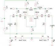
If you want to go back to direct coupling of the
feedback, you can reference R10 and R11 to a
negative DC voltage.
feedback, you can reference R10 and R11 to a
negative DC voltage.
Negative DC ref. for R10 and R11.
I just tryied it out.
It works fine, besides from one thing, the dc-potential between R1 and R14 varies with the outputimpedance (simulated with R3) in the linestage. Is the solution to this problem a DCservo or could there be a more simple way to solve this?
I just tryied it out.
It works fine, besides from one thing, the dc-potential between R1 and R14 varies with the outputimpedance (simulated with R3) in the linestage. Is the solution to this problem a DCservo or could there be a more simple way to solve this?
At this point I definitely would think about replacing the
1 and 8 ohm resistors on the negative half with an
active current source and a -10 volt rail. Less dissipation,
more gain, better input cmrr.
Also, put those zeners on the outside of the gate resistors
or I might be hearing you on my am radio 🙂
1 and 8 ohm resistors on the negative half with an
active current source and a -10 volt rail. Less dissipation,
more gain, better input cmrr.
Also, put those zeners on the outside of the gate resistors
or I might be hearing you on my am radio 🙂
X-SOZ and Active currentsourc
I gess you are wright on this one as well!
I will give it try with the active currentsouce of yours.
Are you listening to radio all day, checking zen-ers?
If you are, you woun´t hear mine, it was a sloopy scematic, sorry, the zeners is sitting on the outside of the gateresistors on my SOZ.
I will go on vacation with my wife for a month or so. You will hear from me again, hopefully not on the radio.
Currentsources for SOZ tail and DC offset.
I have bin given these questions som thoughts.
Isn´t the active currentsource (like the Aleph-one) only useable at the drains?
I have tried simulating a normal currentsource at the tail, and i still have the same problem with DC offset at the input varying with the outputimpedance at the linestage when feedbackloop is DC-coupled.
Well : I have tried the version posted by Ian.
Nelson said : “ The paradox is that feedback is best applied around circuits that need it the least.”
I guess this is the case.
When I read the SOZ article for the first time I said : this is for me!
Now I try it with X and if it is possible , I am more impressed too.
What SOUND.
Ian : The arrangement I posted wasn’t so good performing. Not like this One !
Nelson : thank you for the patience . I am anxious to try the current source .
What current value is preferable?
H Potter when finished your 10W Soz : add 2 resistor and 2 caps and try it .
Stefano.
Simple is often best
Stephano, glad you like the sound of my simple X modified SOZ! Simple is often best from a sonic standpoint if not from an efficiency one. It is a fairly simple matter to drop in a current source for the diff pair 'tail' instead of the resistors. As for the current, it depends on the desired output power and associated power supply voltage. If you already have a working circuit, simply measure the voltage drop across the drain resistors and dive by the value of the resistor. Double this to give the required tail current.
Henrik, I am not sure that Nelson's reference to an active current source was meant to be interpreted as the Aleph current source, though of course I could be wrong. I suspect he simply meant a transistor (MOSFET) one rather than a resistor. It is not at all clear to me how one could take advantage of the Aleph current source in this application. Of course, Nelson could have something else up his sleeve...
Ian.
Of course, Nelson could have something else up his sleeve
Uh Oh...... Poor Mr. Pass now has two unofficial spokesman. Can a career in politics be far behind?
H.H.
Uh Oh...... Poor Mr. Pass now has two unofficial spokesman. Can a career in politics be far behind?
H.H.
A normal (i.e. non-varying) current source is called for beneath the Sources of the output devices. Been there, done that...see SOZ w/current sources thread.
That's not to say that one couldn't use Aleph current sources <i>above</i> the output devices...
Grey
That's not to say that one couldn't use Aleph current sources <i>above</i> the output devices...
Grey
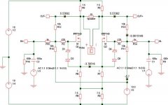
DC at X-SOZ input.
Ian
I have simulated your X-SOSAlt, and i found about -2,5v at the inputterminals with an outputimpedance at a linestage of 100K. This is because, R13, R11, R14 and R4 splits the dc-voltagediff ground/-Vcc/output and leave the -2,5v at the inputterminals. And since the outputimpedance at the linestage is a part of this voltagesplitting it will influence on the given DC at the inputterminals.
To get rid of this DC is my mainocupaton at the moment, you can get around this problem by adding a coupleing cap in the feedbackloop or at the input, but it would be prefereable to make it dc-coupled if possible.
Stefano
You did you use som caps, was it in the input or in the feedbackloop?
Grollins
Nelsons suggestion of using an active currentsource at the tail was (in my oppinion) aimd at solving the DC-problem i had, but i can´t see how it can. It should be possible to use alephcurrentsources at the drains, but that was not what Nelson was talking about. I will go back to read your post on SOZ and currentsources anyway.
Attachments
Variac said:
So you agree that a true Zen doesn't have active current sources.
Despite Nelson steering us toward the active design, I am also really curious about the passive (?) approach.
For ultimate teoretical performance
I would chose a passive.
I have tried it in one of my
most precious designs.
It uses passive bias in a way I have not seen yet.
You can not hear any difference,
but the performance is there.
Would probably not be accepted by "the market".
They are somewhat behind research and ideas
all the time
Thanks for reminding me, Variac
- Home
- Amplifiers
- Pass Labs
- x soz