Re: strasbourg
Do you mean "La Cathedrale"? (the big church)?
what is the dome? 😕ralf said:
...years ago i was in the dome (Munster) of Strasbourg - very impressive..
Nice to comunicate with fanatics all around the world - internet life high..
Ralf
Do you mean "La Cathedrale"? (the big church)?
Henrik said:Bricolo
If You look at the original scematic of the SOZ and compare it with my version of XSOZ, then You will know the difference.
To fully understand the X thing is something else, You can read about it in Nelsons patent, but it can be hard to understand.
If I can explain it in other way than NP did in the patent I will post it, and then we will se if my understanding is correct. Funny, nobody has yet given the fully logical explanation in laymans word, if somebody has, let me know.
No, if I compare the SOZ shematic anr yours, I will see the differences, but not understand them 😉
For sure, I haven't understood X. When I look at Nelson's patent, I find it quite complicated, when I look the aleph X shematics, I find it very different from the patend, they haven't anything in common, IMHO (the aleph X has "crossed" feedback, the patent hasn't)
And when I check the X-SOZ shematic, I think that X is only a concept, telling that X is only a basical feedback, but on a balanced amp (a fully symetrical amp)
But that's not the problem.
The thing I was asking you, is to tell me "I've changed resistor ... value, because of ....", "I've added this resistor, to do this..."
Because for now, I only see the differences, and I don't have the knowledge to understant them.
And your explanations would really help me much 🙂
Re: Re: strasbourg
..yes
Ralf
Bricolo said:what is the dome? 😕
Do you mean "La Cathedrale"? (the big church)?
..yes
Ralf
How X
I will try to explain the X in XSOZ.
To add X to the SOZ as I did it, all you need is to add C1, C2, R212, R 213, R214, 215, reduce R208/209 from 220 to 100 Ohm and a preamp that can feed a load at only 120 Ohm.
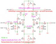
C1 and R212 form the feedback from drain to gate at Q201.
C2 and R213 form the feedback from drain to gate at Q202.
When we apply Negative Feed Back, the signal source will se this as a lower input impedance or higher load, since every time the signal source wants to deliver a certain voltage the NFB wants to lower that voltage. But if the signal source is ideal, witch means it will keep the voltage level regardless of the load, it will not be affected, and no NFB will be added. So in order to get NFB and X we need to add some impedance to the signal source so it can vary with the NFB presented to it, and that we will do by placing R214 and R215 between node 1 and node 2 in the circuit, so that is why they are in XSOZ and not in the original SOZ.
This is just normal feedback, but in case of the X this is not so important. The far more important thing is, that when placed in a differential (not only balanced) gain stage like the SOZ, this NFB also opens a path for the noise and distortion produced by the gain in Q201 to the drain of Q202, and it arrives here non-inverted, witch means it will be cancelled differentially.
This path goes from node 3 through C1, witch blocks the DC, and through R212 witch will, in cooperation with R214, adjust the NFB level at node 2. From node 2 it passes the gate resistor to the gate, and then leaves Q201 in Common Drain*) mode and arrives at Q202´s source pin as if it was coupled in Common Gate*) mode and then appears amplified at it’s drain.
All along this path the noise/distortion keeps the non-inverted mode. When the noise/distortion arrives in identical mode to the output it will be cancelled differential, the speaker will not see it, but measured single ended it’s still there.
Signal path hits the nodes: 1-2-3-4-5.
X path for Q201´s noise/distortion hits the nodes: 3-2-4-5.
I have just described what happens to a signal presented to +IN, but the same will happen for –IN, and XSOZ should not be driven unbalanced!
In the Aleph-X it is the input diff. pair witch realizes the X, but both feedback loops includes it’s own Aleph output stage. Thus the diff. pair don’t need to be biased within the high output current, witch saves a lot of heat.
Quoting Nelson:
The essence is still using a symmetric feedback arrangement
around a differential pair, which isolates error from signal
and uses it to make distortion on two halves identically
in phase and thus cancelled.
Can’t be said more precisely by the man himself who got this brilliant idea.
*) See Nelsons article “DIY Op Amps” fig.6.
BTW my XBOSOZ is getting slightly better for every 24 hours of idling.
I will try to explain the X in XSOZ.
To add X to the SOZ as I did it, all you need is to add C1, C2, R212, R 213, R214, 215, reduce R208/209 from 220 to 100 Ohm and a preamp that can feed a load at only 120 Ohm.
C1 and R212 form the feedback from drain to gate at Q201.
C2 and R213 form the feedback from drain to gate at Q202.
When we apply Negative Feed Back, the signal source will se this as a lower input impedance or higher load, since every time the signal source wants to deliver a certain voltage the NFB wants to lower that voltage. But if the signal source is ideal, witch means it will keep the voltage level regardless of the load, it will not be affected, and no NFB will be added. So in order to get NFB and X we need to add some impedance to the signal source so it can vary with the NFB presented to it, and that we will do by placing R214 and R215 between node 1 and node 2 in the circuit, so that is why they are in XSOZ and not in the original SOZ.
This is just normal feedback, but in case of the X this is not so important. The far more important thing is, that when placed in a differential (not only balanced) gain stage like the SOZ, this NFB also opens a path for the noise and distortion produced by the gain in Q201 to the drain of Q202, and it arrives here non-inverted, witch means it will be cancelled differentially.
This path goes from node 3 through C1, witch blocks the DC, and through R212 witch will, in cooperation with R214, adjust the NFB level at node 2. From node 2 it passes the gate resistor to the gate, and then leaves Q201 in Common Drain*) mode and arrives at Q202´s source pin as if it was coupled in Common Gate*) mode and then appears amplified at it’s drain.
All along this path the noise/distortion keeps the non-inverted mode. When the noise/distortion arrives in identical mode to the output it will be cancelled differential, the speaker will not see it, but measured single ended it’s still there.
Signal path hits the nodes: 1-2-3-4-5.
X path for Q201´s noise/distortion hits the nodes: 3-2-4-5.
I have just described what happens to a signal presented to +IN, but the same will happen for –IN, and XSOZ should not be driven unbalanced!
In the Aleph-X it is the input diff. pair witch realizes the X, but both feedback loops includes it’s own Aleph output stage. Thus the diff. pair don’t need to be biased within the high output current, witch saves a lot of heat.
Quoting Nelson:
The essence is still using a symmetric feedback arrangement
around a differential pair, which isolates error from signal
and uses it to make distortion on two halves identically
in phase and thus cancelled.
Can’t be said more precisely by the man himself who got this brilliant idea.
*) See Nelsons article “DIY Op Amps” fig.6.
BTW my XBOSOZ is getting slightly better for every 24 hours of idling.
Attachments
great 🙂 thanks a lot!
How did you calculate the values for C1 anr R212? Is there a "common" value for feedback?
R207 has been removed (bypassed), won't this degrade THD?
How did you calculate the values for C1 anr R212? Is there a "common" value for feedback?
R207 has been removed (bypassed), won't this degrade THD?
Bricolo
How did you calculate the values for C1 anr R212?
I did it in the SIMEtrix simulator, there I could follow the amps behaviour under varying circumstances.
Is there a "common" value for feedback?
Almost, as long as you keep inside the normal impedance ranges, this was not possible here. The Aleph-X uses almost standard values I suppose.
R207 has been removed (bypassed), won't this degrade THD?
It should, but I think the X will cancel most of it. The X-feedback needs this extra gain. I haven´t measured THD, but as long as the sonical change is for the better it´s ok, and they are I can tell.
Henrik
Thank you for your kind explanation. And, I am sure that you are satisfied with the sonic performance of your XSOZ. By the way, I have two questions with your circuit posted above.
Thank you for your kind explanation. And, I am sure that you are satisfied with the sonic performance of your XSOZ. By the way, I have two questions with your circuit posted above.
- From the circuit, I see that you have the feedback of the output signal into the input after changing the phase by C1 and C2. As far as I understand, however, the feedback is to be without changing the phase for the purpose of the X distortion cancellation. Don’t you think so?
- Since you have C1 and C2, your feedback becomes positive feedback to the input on the same side. That is why the resistor values of R212 and R213 are relatively small. Is it right?
[/list=1]
JH
Henrik,
I had a SOZ, and modified to X-SOZ using Ian Macmillan's configuration. I tried to test your configuration during Christmas time and found that it did not work.
The voltage swing from the differential output is extremely limited, clipping appeared, and the overall gain is less than 1. I checked several time but cannot find any assembly error. I immed switched back to Ian's configuration and it worked again perfectly. The only difference between your configuration and Ian's is that you block the DC in the NFB loop, and the gain control resistor pair is low (1k - 82 ohm). In Ian's circuit, the NFB is DC, so we need to put in blocking capacitor in the inputs, and the gain control resistors are (10k - 1k). Any idea why?
JH
1)Caps don’t change the phase, they only blocks DC.
Without NFB node 2 would have +1V just like at node 1. The NFB is -0.5V at node 2 (-5V at node 3 is lowered by R212 at node 2) and the signal is +1, so total is +0.5V (1-0.5).
The non inverted noise and distortion will be lowered by a factor of 10, just like the signal, but since there this is not a part of the input signal, it will not be lowered but go direct to the gate and appear at the source pin at Q1. From here it will be amplified by Q2 as Common Gate amplification with output at the Drain, all in non inverted mode and the noise and distortion will appear in common mode at both output terminals and thus cancelled differentially.
2)The small values of R 212 and R214 are needed in order to obtain a high frequency roll at -3db at 100kHz.
Ian Macmillan’s and my first XSOZ made it only to 75kHz at -3db and more important only 25kHz at -2db. This was certainly audible.
The price paid for the low values of R212 and 214 is very very low input impedance; 120-Ohm single ended, normal standard is 10K to 47K Ohm. This requires a very special preamp to drive this lower load, BOSOZ and BOZ can’t.
FYC
Sure it works.
All you need is a proper preamp to drive it; your missing voltage swing would properly be caused by the low input impedance at the XSOZ, that almost shortens the output from your preamp and thus makes it clipping and producing a lot of distortion, and then sounding awful. That was why I had to make the XBOSOZ; even the BOSOZ can’t drive my version of the XSOZ.
If you have a proper preamp, the sound is so much better than the Ian Macmillan’s “Ian-X-SOZAlt” or my first XSOZ witch was based on Ian’s values for R212 (10K) and R214 (1K).
When the caps is inside the X-feedback loop, their noise and distortion will be cancelled as well, if they are outside the feedback this will not happen.
Herik
I was totally wrong about the changing phase. I was in a condition out of order.
You have done your best to get almost complete cancellation of the nonlinear distortion by introducing the X-tech, and particularly with a combination of low value of R212 and higher value of R210. It also explains me that you have been trying to sacrifice the signal gain somewhat and, by doing so, to maximize the distortion cancellation.
By the way, you have said, when the caps are inside the X-feedback loop, their noise and distortion will be cancelled as well. What kind of noise and distortion is produced by the caps?
Since the input impedance of your XSOZ is very low, the pre might be overloaded or, as you have said, the output of the pre might be considered almost shortened. In this respect, your only XBOSOZ will work properly. However, if I want to use other than your XBOSOZ, what factors are to be deeply considered as matching preamplifiers?
Your brief explanation would much appreciate.
JH
JH
Velcome back in order!
R210 has the same value as suggested by NP in the SOZ.
I have sacrificed no gain, my XBOSOZ and XSOZ have exactly the same gain as NP´s original designs.
Any passive or active components produces some unlinearity witch causes more or less distortion and they also produces some noise, even wires, but not that much.
I have to leave now, I will try to ansewer your last question later today or tomorrow.
JH
The output impedance in my XBOSOZ is 10 Ohm as I recall.
The pramp for my XSOZ shoud have between 10 to say 100 Ohm outputimpedance.
The specific need is an output swing at around 1.5V at 15mA current, wich is more current than most preamps is capable of.
WWW.LCAudio.dk has a preamp called SideWinder, wich can do this, Lars Clausen even recommend to solder a 150 Ohm resistor at the interconnect at the poweramp from signal to gnd. You can read about this at his homepage.
If the preamp´s outputimpedance is 12K and the poweramp inputimpedance is 120 Ohm, then I woud say that the output it is almost shortend. But if the preamp´s outputimpedance is 12 Ohm, it is far from shorted when loaded with 120 Ohm.Since the input impedance of your XSOZ is very low, the pre might be overloaded or, as you have said, the output of the pre might be considered almost shortened. In this respect, your only XBOSOZ will work properly. However, if I want to use other than your XBOSOZ, what factors are to be deeply considered as matching preamplifiers?
The output impedance in my XBOSOZ is 10 Ohm as I recall.
The pramp for my XSOZ shoud have between 10 to say 100 Ohm outputimpedance.
The specific need is an output swing at around 1.5V at 15mA current, wich is more current than most preamps is capable of.
WWW.LCAudio.dk has a preamp called SideWinder, wich can do this, Lars Clausen even recommend to solder a 150 Ohm resistor at the interconnect at the poweramp from signal to gnd. You can read about this at his homepage.
Henrik
I do have a XBOSOZ as my pre-amp to drive the XSOZ, but still get the limited swing. The XBOSOZ is also based on your schematics. Something strange here.
I do have a XBOSOZ as my pre-amp to drive the XSOZ, but still get the limited swing. The XBOSOZ is also based on your schematics. Something strange here.
Henrik
Thanks to your explanation, now I have better understanding how to match pre amps with power amps having very low input impedance.
Regarding the noise and distortion generated by caps, I was thinking about how they are bad against the sound quality. It seemed that my thought and the question however went amiss. Anyhow, I agree that when the nonlinear distortion output voltages produced by the gain transistor and the DC-blocking cap are fed back as noninverting voltages to the inverting input, they will be calceled almost null at the output stage. At the same time, if I see your XSOZ, it has not only noninverting voltage feedback, but also inverting voltage feedback which would lower the input impedance--probably very low due to the low R212. I hope I am right...
Simply, I thought that your XSOZ and the original SOZ have similar or the same output power ratings, but different signal voltage gains...???
JH
FYC
Simple test:
I presume that your system is working at this moment, with Ian Macmillan´s XSOZ.
If so, try to short the output of your XBSOZ to ground with a resistor at say 150 Ohm while stil connected to your poweramp. If this don´t give you any problems, then your XBOSOZ is ok, and then the failure has been in your build of the XSOZ in my version.
If you get the same problems as you did before, then it´s proberly a failure in the XBOSOZ.
JH
I will be back again.
what can we do to make the bosoz less sensible to the load? (I mean: keep the peak to peak output voltage quite stable, with a low impedance load, or a high one)
JH
I have reconsidered the question about the cancellation of noise and distortion from the caps inside the X-loop in the XBOSOZ, I am afraid this won’t happen, because it is not present at the output at node 3, it is more like a new signal source at the input node 2.
If you move it to the front of the input, you would need to increase the value significant in order to get the same low-end roll off, so it is still better to keep them inside the feedback loop. You also get a lower bias point for the fet´s which gives a little more voltage swing, but this could also be adjusted otherwise.
Bricolo
Lower the drain resistors and raise the gain by reducing R15.
More efficient, make it an XBOSOZ, the X-feedback alone will lower the output impedance dramatically and then you also get X
But it isn’t like that.Simply, I thought that your XSOZ and the original SOZ have similar or the same output power ratings, but different signal voltage gains...???
I have reconsidered the question about the cancellation of noise and distortion from the caps inside the X-loop in the XBOSOZ, I am afraid this won’t happen, because it is not present at the output at node 3, it is more like a new signal source at the input node 2.
If you move it to the front of the input, you would need to increase the value significant in order to get the same low-end roll off, so it is still better to keep them inside the feedback loop. You also get a lower bias point for the fet´s which gives a little more voltage swing, but this could also be adjusted otherwise.
The signal is inverted in the feedback, but the noise and distortion is noninverted.At the same time, if I see your XSOZ, it has not only noninverting voltage feedback, but also inverting voltage feedback, which would lower the input impedance--probably very low due to the low R212. I hope I am right... ...???
Bricolo
Lower the drain resistors and raise the gain by reducing R15.
More efficient, make it an XBOSOZ, the X-feedback alone will lower the output impedance dramatically and then you also get X
As you have said earlier, I think that the distortion produced by the cap inside the feedback loop will be cancelled too. Anyhow, it does not matter whether it is actually cancelled or not, as the size of distortion is expected ignorable, IMHO. I will consider the caps with respect to the frequency bandwidth only.I have reconsidered the question about the cancellation of noise and distortion from the caps inside the X-loop in the XBOSOZ, I am afraid this won’t happen, because it is not present at the output at node 3, it is more like a new signal source at the input node 2.
IMHO, both signal and the noise/distortion output voltages are fed back as noninverting voltages to the inverting input, with respect to the noninverting input of the signal. And the noise/distortion voltages are amplified and arrive at the output with inverted phase, cancelling the original noise/distortion. In addition, the input impedance is increased with this kind of feedback.The signal is inverted in the feedback, but the noise and distortion is noninverted.
At the same time, both signal and the noise/distortion voltages are also fed back as inverting voltages to the noninverting input. The noise/distortion is decreased in this case too, but the input impedance is decreased in opposition to the above.
Don’t you think so?
JH
- Home
- Amplifiers
- Pass Labs
- x soz