Updated Revision 1
An identification name, XSOZV2, is given to the circuit.
If this ID name gives you a confusion, I will change it at your request.
A brief description about the circuit is as follows:
JH
An identification name, XSOZV2, is given to the circuit.
If this ID name gives you a confusion, I will change it at your request.
A brief description about the circuit is as follows:
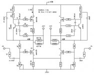
- MOSFETs are to be properly matched.
- Bias current is about 1.32A.
- R20 is set to 3 Ohms, which could provide the tail of current source reasonably stiff.
- The input resistor R2 is set to 1k Ohms. This could be adjusted later, if required by the source output.
- The drain voltage of Q1 is set to +18V for an AC voltage swing of about +/- 14V. These closely depend on the supply DC voltage and the size of the tail resister.
- R16 is set to 1.5K for a 30% AC fraction. This could be adjusted later for a proper speaker damping.
JH
Attachments

Is C2 (10µF) really necessary?
Why not using the input-circuit of Henrik? It looks more SOZ like.
How much output power do you expect from the schematic above?
regards
Günter
Why not using the input-circuit of Henrik? It looks more SOZ like.
How much output power do you expect from the schematic above?
regards
Günter
Nelson wrote:
-Of course the Zen and SOZ were made as simple as possible -partly because that creates an attractive starting point for DIYers.
Well.... you are RIGHT! that's what got me into this crazy world
-In my test amps, I get about 30%, meaning that a 30 watt
-output will idle at 100 watts.
This really does appeal-house wiring becomes an issue if higher power is needed using the resistive loading!
I've studyed my motives and realized that I am prejudiced in that what I have accomplished to this point is mounting 32, 50 watt power resistors to heatsinks! Thanks to Henric's wonderful test diagram I can see how to make the various versions. He MUST make a diagram if any other scheme becomes preferred!
I have now decided that I can do my SOZ and later add the constant current sources with a big switch to change from one to the other depending on my mood.
Go for it!!, but don't forget the preamp issue!
XSOZV2 R1
occasionally busy night on duty for wife’s ecstasy…
- Stefanobilliani, I am happy with your praise.
- Selfmade, C: Yes or no. It seems up to the personal preference.
- Selfmade, Power: I hope 25W/ch with 8-ohm load.
- Selfmade, Input circuit: I am notoriously ignorant about the input buffer. Inned more study.
- Lieven, Sustained bias plateau of xsoz?: Probably.
occasionally busy night on duty for wife’s ecstasy…
C2 is essential as a practical matter.
Driving this circuit single-ended is not recommended, but
it will work, sort of. Optimally the diff pair is biased by a
current source. You can do this with just a couple of volts
loss, so it's practical.
😎
Driving this circuit single-ended is not recommended, but
it will work, sort of. Optimally the diff pair is biased by a
current source. You can do this with just a couple of volts
loss, so it's practical.
😎
XSOZV2 R1
Yes... Nelson Pass, C2 is essential for the practical feedback.
By the way, Nelson, XSOZV2 is one of your properties.
It looks like a simple circuit, but the following three are there all in one.
Otherwise, it is too heavy to me because I am already wanted, $$$, by 6 girls.
😎
Yes... Nelson Pass, C2 is essential for the practical feedback.
By the way, Nelson, XSOZV2 is one of your properties.
It looks like a simple circuit, but the following three are there all in one.
- Zen V2
- Pass Patent #
- Pass Patent #
is still valid.as a matter of policy we do not concern ourselves with DIY efforts
Otherwise, it is too heavy to me because I am already wanted, $$$, by 6 girls.
😎
I'm sure it will amuse you to know that I have 5
attorneys. Whenever somebody wants me to do
some work, I charge the same rate as the most
expensive of them.
😉
attorneys. Whenever somebody wants me to do
some work, I charge the same rate as the most
expensive of them.
😉
Yeah, it is amusing enough.5...?!

I meant converting unbalanced signal to balance thru (X)SOBOZDriving this circuit single-ended is not recommended, but
it will work, sort of.
and feeding the balanced signal to XSOZV2. Now quite acceptable...? Please...don't say no.
 if we bias the diff pair with a current source.
 !!!
!!!
jh6you
This topic has been popping up about once every four months for the past 2 years so you maybe aware of it. You shouldn't expect miracles from this circuit. The BOSOZ is not a great unbal-to-bal converter, actually a user has already posted simulations of the circuit that quite clearly show different voltage levels from the hot and the cold outputs when the cold input is unused, or grounded, in SE operation. The same guy has already posted a version with current source which performs better "instrumentally". If you want a Pass original circuit you could go for the AlephP that has a full complement of current sources.
This topic has been popping up about once every four months for the past 2 years so you maybe aware of it. You shouldn't expect miracles from this circuit. The BOSOZ is not a great unbal-to-bal converter, actually a user has already posted simulations of the circuit that quite clearly show different voltage levels from the hot and the cold outputs when the cold input is unused, or grounded, in SE operation. The same guy has already posted a version with current source which performs better "instrumentally". If you want a Pass original circuit you could go for the AlephP that has a full complement of current sources.
Grataku
Well noted your comment. If my post escalated a monotony and boredom, I am very sorry for it. All right, I will trace back the old issues carefully for a study.
Please note that with the post I am not arguing BOSOZ is a miracle or not. I have no ability or know-how to do such big thing. My interest is in a small thing. I would like to know which preamp is having acceptable function as a converter for unbalanced input and balanced output. I just wanted to know whether BOSOZ is acceptable or not. The main reason why I attached the circuit was not to be proud of it, but for an easier communication.
I do not want Aleph P. I want a simpler one. What do you recommend for my purpose?
Please come back.
As you shrink the value of R15 on your circuit, it
will become a better unbalanced to balanced converter,
and you only need deal with the additional gain
produced.
Or you can use a current source. Or you can increase
the negative supply voltage and use greater resistor
values biasing the diff pair.
will become a better unbalanced to balanced converter,
and you only need deal with the additional gain
produced.
Or you can use a current source. Or you can increase
the negative supply voltage and use greater resistor
values biasing the diff pair.
Nelson, please let me walk out of the issue about BOSOZ after this.
Your three alternatives explain me that the current source is the key.
I would try all three someday. Today, however, I am engaged to
the 1st alt only. Here is my new plan.
Your three alternatives explain me that the current source is the key.
I would try all three someday. Today, however, I am engaged to
the 1st alt only. Here is my new plan.
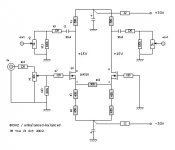
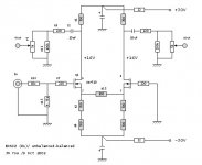
- DC supply kept of +/-30.
- Bias current reduced down to ~20mA.
- The values of tail resistors increased.
- The value of R15 decreased for a convincingly stiff current source.
- The high gain attenuated at the input with a voltage divider.
- The volume planned at the output.[/list=1]Question: If I shrink the value of R15 further down to 47 ohms,
would it be even better? If yes, I should also change the input voltage
divider from 10k/4.75k to 12k/2k. Is the 2k, if connected to the ground,
too small? Thanks.
JH
Attachments
This will make it better in terms of the output
balancing, but I think at some point you have to
look at why you are trying to achieve a perfectly
equal output amplitude on both halves. If your
amplifier has an ordinary balanced input, it is not
of any particular value in terms of improving the
noise rejection, since the noise will be identical
on both sides regardless.
Unless you go to a constant current source for this,
you will continually be trading off some other
performance parameter such as noise and distortion
against the degree of output level matching.
If you want to continue to use resistors for biasing, you
probably have made as much improvement as you
need or want.
When I evaluate deflections and stresses of ships for my
profession, the first thing I do is checking balanced force at the
one reaction point whether the reaction force is zero. It is to be
zero. If it is nonzero, means unbalanced and there are always
certain degrees of error in the results.
All right, I will go for the constant current source tails,
based on your advice and to have the strong foundation.
I will come back for your positive feedback. Takk!
You shoud check the relation between outputimpedance of your BSOZ and the inputimpedance of your X-SOZ. I havent simulated or calculated your suggestions, but i beleve that you will get a highend roll off at -1db at around 20kHz, wich is too low in my oppinion.
I coud be wrong, but check it!
I coud be wrong, but check it!
- Home
- Amplifiers
- Pass Labs
- x soz