Circlotron said:
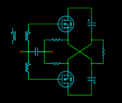
I think there is a lot to be said for N-channel-only output stages. You can make them perfectly symmetrical (to the eye at least) this way: Instead of driving the same end of the load alternate directions, just drive alternate ends of the load the same direction. Works for me.

Like this ?
With a little more bias also works in 4 ohm loads.

Nifty cct!Bernhard said:Like this?
I was thinking like this, the cct they named after me.
DC supply connections to electro's not shown.
Attachments
Nelson Pass said:We refer to the Aleph as single-ended because the gain
for the signal comes from only one side. Even though the
current source is active, it is not literally part of the gain path.
We refer to the Aleph X amps as "balanced single-ended" a
term coined by another manufacturer some years ago, referring
to two single-ended amplifiers operating differentially, forming
balanced outputs.
Like the SOZ, technically this would be thought of as push-pull,
although not in the usual sense.
 I still do not understand this.
My view: (May be complete nonsense)
The current source is modulated by the output signal.
When the gain Fet conducts 50% more, the cs Fet conducts 50% less, and vice versa.
So the current source is a (third) gain stage.
The whole amp gain is set by the feedback values ( external circuitry if we look at the amp as an op amp ).
There is not added total gain to the amp by making the cs active, but the gain inside the feedback loop is split between the gain Fet and the cs Fet.
Also the 220uF caps carry the signal to the cs, and as the cs provides part of the output signal, the 220uF electrolytic caps are in the signal path.
Also the current curves through the 0.47ohm resistors look exactly like the ones of classA puspull.
I know, from the point of view that the amp will be clipping when the demanded (from the cs) current is over the limits of 0% and 200% of idle current, it is a single ended circuit.
😕
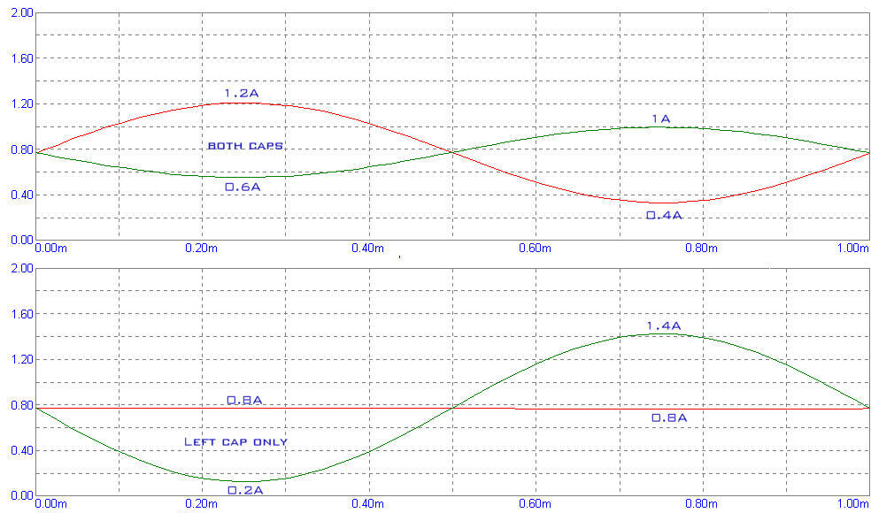
Simulation of the Aleph3 with active and static current source.
In the upper diagram the original Aleph3 and in the lower diagram the Aleph3 with the right 220uF cap missing.
Red is current through cs Fet, green is current through gain Fet.
We can clearly see that when the current source is active, it takes part of the job of the gain stage.
So does it have gain or not ?
I can't really explain, but it confuses me a little that there are two feedback paths, one direct from the gain stage fet, and one from the current source, which is driven by the gain stage that was already fed back to the amp's differential input.
Bernhard,
Your circuit is very clever. In outline I understand it well enough; the fine detail would require some concentrated study on my part to fully comprehend. That's real neat, man!!
I find it helps to think of current and voltage control as separate beasts in these circuits.
In your circuit, the upper mosfets, acting as source followers, control the voltage which presents at the voice coil. They are thus the 'signal path' devices which Nelson alludes to, and they therefore control the sonics of the amplifier since it is solely their voltage output determines the reaction of the voice coil and, incidentally, the feedback regime.
The lower mosfets, however, supply current. As variable current sources, they supply current under the tight control of the voltage present at the sources of the upper mosfets.
The source voltage of the upper mosfets in turn dictates a current supply through the voice coil. This current requirement is completely met by upper mosfets on the positive half cycle, and by the lower mosfets on the negative half cycle. The egg is the upper devices; the chicken is the lower devices - the order of control is significant, and there lies the rub.
Therefore, the sonic outcome will be principally determined by the upper devices, and their configuration, in this case source follower, with global negative feedback for correction. If the lower mosfets always act under the control of the uppers, then they can logically have no direct influence over the sonics. Consequently, the topology is truly single-ended, though differential. This has interesting repercussions.
When a circuit is truly single-ended, and not differential, any distortions will normally be asymmetrical, that is, the upper and lower waveforms will not be entirely symmetrical. This defines second harmonic distortion, and sounds full and warm, that typical tube sound. If the distortion is identical for upper and lower half cycles, as it usually is for a differential circuit, then the distortion so produced is odd order, primarily third, and this sharpens the sound, although it is still musical. Further higher harmonics, often produced as a spray of artefacts at H5, H7, H9 etc sound terrible, as they are NOT musical, and give that grainy, fatiguing sound so typical of most SS amplifiers.
A differential drive system such as your circuit will promote symmetrical distortion because by its nature it will cancel even order harmonics. The result will be a skewing towards the H3 rather than the H2 end of the harmonic spectrum; this will show as a very clean, pure sound, but there will be a faint irritation in the presentation during a long listening session. For this reason, I am loathe to go down the differential path, although I know plenty of amps using this topology which sound pretty good, such as Nelson's own X amps, I believe, and a number of significant tube designs.
To my thinking, and I'm only one guy who could well be quite wrong, the optimum arrangement is a single ended configuration, not differential, with sliding bias. This gives grace to the sound, primarily H2, and high efficiency as well. You have implemented sliding bias here, and I think it is VERY clever, but (at least to me!) negated some of the efficiency benefits by using a differential drive. I am certainly aware of the great appeal of bridge circuits, so-called circlotrons, beloved of Graham (who I believe, having met and talked with him at length, is a nascent genius), but I honestly believe that for the foregoing reasons they tend to play down the H2 at the expense of H3. I prefer to see the proportions reversed; typically 35dB down on H2 and 45dB or so down on H3. Sonically, this gives the best presentation of the lot, but can only be done with single-ended circuits. The sliding bias regime, something I'm working on frantically at present, is the hard part, as it has adverse repercussions for stability. I call it 'The Taming of the Shrew', and it's my greatest intellectual challenge to date.
I hope this is useful; there are so many ways of looking at this problem I think it is important to consider them all.
Brilliant circuit, BTW. I'm very impressed by the thinking.
Cheers,
Hugh
pictures of single-ended and X-system
http://www.dynabody.com/hgym/latmachine.htm
this is a single ended class-a type. Notice the pre-tension when you are sitting down holding the bar.
http://www.dynabody.com/hgym/cablecross.htm
this is the class-a X-amp: pre-tension on both sides if positioned in the middle using both grips. Also notice the "X", this is the upper bar, used to hold both amps in the same position relative one to another.
AKSA said:In outline I understand it well enough; the fine detail would require some concentrated study on my part to fully comprehend.
The lower mosfets, however, supply current. As variable current sources, they supply current under the tight control of the voltage present at the sources of the upper mosfets.
Therefore, the sonic outcome will be principally determined by the upper devices, and their configuration, in this case source follower, with global negative feedback for correction. If the lower mosfets always act under the control of the uppers, then they can logically have no direct influence over the sonics.
For this reason, I am loathe to go down the differential path, although I know plenty of amps using this topology which sound pretty good, such as Nelson's own X amps, I believe, and a number of significant tube designs.
To my thinking, and I'm only one guy who could well be quite wrong, the optimum arrangement is a single ended configuration, not differential, with sliding bias. You have implemented sliding bias here, and I think it is VERY clever, but (at least to me!) negated some of the efficiency benefits by using a differential drive.
Hugh,
Thanks for the detailed explanations. Some new points of view for me…
My knowledge of amp building is very young, I started on the beginning of the mono susy amp thread...
I think you understood the circuit already completely.
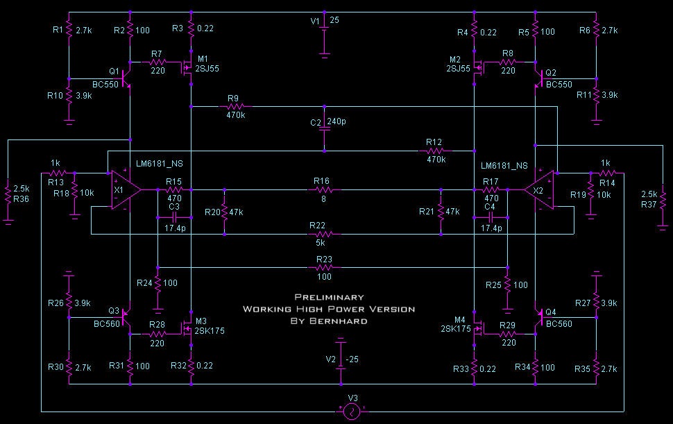
For those who may be do not… here again:
If a positive signal appears on the left input, the amp follows the positive voltage of the op amp output via the upper left Fet.
On the right side the amp follows the negative voltage of the op amp output via the right upper Fet.
The bias of the lower left Fet is determined by the voltage divider network, connected between negative rail and virtual ground ( virtual ground is presented by the amp’s outputs on "no signal" ).
The consequence is that the gate voltage of the lower left Fet goes more negative, following the amp’s right side output.
So the lower left Fet conducts less current, while the upper left Fet conducts more.
For the other side everything is vice versa.
Lower and upper Fets conduct the same current without input signal, with input sine signal the upper Fet conducts more while the lower Fet conducts less and vice versa.
Do the lower mosfets really always act under the control of the uppers ?
Under control for shure, but how far ?
Isn’t the voltage controlled current source an additional nonlinear element that needs correction by feedback, as is/does the voltage follower ?
Another gain stage ?
What is a SS amplifier ???
So You advice to not use a bridged amp.
This could be an advantage for me, as I also need to drive a tube which is a problem with a bridged amp.
Greetings, Bernhard
Bernard,
the source follower pull-down currents are modulated by the output voltage not by the current supplied to the load (ie the Id of the followers). What happens when the load is not a pure resistance?
You could turn an Aleph current source upside down and use it in this application. It would modulate with the output current.
Regards
13DoW
13DoW said:the source follower pull-down currents are modulated by the output voltage not by the current supplied to the load (ie the Id of the followers). What happens when the load is not a pure resistance?
Dow130,
You frighten me

A 2mH in series with the load distorts the output voltage, but it also does it on Aleph and another tested circuit, the sim says that.
Nelson mentioned that before, I did not pay attention 🙁
I will think about this, but anyway my speakers are active, so there are no crossover networks and bad impedances to drive

Hi Bernhard,
2mH is the same order of magnitude as a voice coil.
It may we worth considering a 100nF and 10R in series from each output to ground to correct phase angle disturbances due to inductive loading with a voice coil.
Oh, and a voice coil is a 'nasty impedance', there's no getting away with it! You really need to strap 10R and 4.7uF across most drivers to compensate this inductance and keep the impedance relatively constant across the audio band.
There are a couple of reasons for this. Firstly, a changing impedance at the load will change Open Loop Gain, and thus feedback factor. This is not good. Secondly, changing phase angle on the driver will destabilise most feedback amps because it modifies the pole point, and correcting this phase shift reaps benefits for stability.
Cheers,
Hugh
Bernard,
what I'm thinking is that you want the current source pull-down of one side to increase in harmony with increasing drain current from the source follower on the other side.
What I fear is that to get this to work properly you should monitor output current change and not output voltage change. An extreme test case would be to replace the 8Ohm load resistor with a current source. Then, with the differential output voltage fixed, sweep the current source from zero up to a reasonable value (eg. 2A).
The current source will be able to pull an extra 2A through the source follower but there will be no change in amplifier output voltage (excepting the change due to follower Vgs) hence there will be no signal to increase the pull-down current on the other side so it will have the normal DC bias current.
As long as the load is purely resistive then the change in output current is reflected by the change in output voltage but if, during a transient, the load impedance dropped and more current is demanded for the same output voltage then the pull-down current source may not fully compensate.
Regards
13th Duke of Wymbourne
Bernhard,
The 13th Duke, Bless Him, is right on this I believe. You really want to increase CS flow from current in the opposite source follower, not from voltage.
It is true that the current is generated by the voltage, and that a voltage signal should give you the necessary current increase on the oppositive side which is dealing with the negative half cycle. However, since the load is reactive, you cannot guarantee that the two will be exactly in step, as they would if the load were purely resistive.
This throws you into murky water. You need a current servo, which is harder to arrange. However, it's possible.
How about set up a voltage reference wrt the negative rail for each CS (current sink)? With a 0.33R source resistor, and passing say 2A, you would need a gate bias of about (3.6 + 0.7) = 4.3 volts. This bias voltage, generated by a couple of LEDs or some other simple circuit, could be communicated to the gate via say a 4K7 resistor, plenty small enough for good control, yet not so large self-oscillation might become a problem.
Then you need to arrange for the CS to be sensitive to current flow in the opposite side source follower. You have a 0.33R resistor in the drain circuit of each source follower, so how about an electro 22uF cap from the drain of the source follower down to the gate of the CS on the SAME SIDE? Thus, as current increases on say the left side SF, for the positive half cycle, the voltage at the drain of the left SF drops, and this reduces the current on the associated CS. Correspondingly, at the same time on the right side, as the current decreases on the right side SF, it's drain voltage rises slightly, and this increases flow through the right side CS, exactly as required.
This is, like your idea, effectively a sliding bias regime, except that it is now solely current servoed. The idea is not mine; Doug Self has discussed it at length here at the bottom of the page: http://www.dself.dsl.pipex.com/ampins/discrete/cfp.htm
You could expect to maintain drive and distortion specs at about half the expected quiescent, which is excellent for efficiency, and the benefit, as you have doubtless figured out, is that the idea can be transposed to single ended operation without difficulty.
Cheers,
Hugh
Hugh, Duke,
I believe you and Nelson
Even if I still can't understand it completly, as I mentioned before, in the sim with 2mH + 8ohm the effect on the output voltage looks pretty the same on Aleph3 and my circuit.
To sense the current via a cap came to my mind also, but it was my objective to get rid of Aleph's electrolytics...
As you both say that it is so important that the waveforms are both absolute symmetric, and the signal passes these electrolytics 😱
😱  for me it is clear that they have the same bad influence on sound as if they were coupling caps on the input of the amp.
I will look on the sim with squarewave and 2mH...
Greetings, Bernhard
I believe you and Nelson
Even if I still can't understand it completly, as I mentioned before, in the sim with 2mH + 8ohm the effect on the output voltage looks pretty the same on Aleph3 and my circuit.
To sense the current via a cap came to my mind also, but it was my objective to get rid of Aleph's electrolytics...
As you both say that it is so important that the waveforms are both absolute symmetric, and the signal passes these electrolytics
😱 for me it is clear that they have the same bad influence on sound as if they were coupling caps on the input of the amp.I will look on the sim with squarewave and 2mH...
Greetings, Bernhard
Hi Bernhard,
Actually, I have a surprise for you! 😉
The electro carries the current sense signal. It tells the CS mosfet to increase its current throughput to keep up with demand, as dictated by the voltage at the source of the upper mosfet.
This highlights the extraordinary thing about this topology. The upper mosfet sets the voltage, and thus the sonics, since voltage on the voice coil is the name of the game. As long as the current through the voice coil is set by the voltage demand at the load (viz the source of the upper mosfet), then the actual current is not too important.
Why? Because any minor discrepancies in current at the lower mosfet will merely show up as great or lesser quiescent flow through both devices.
Thus we have the weird situation that the electro, with all its dielectric absorption and poor frequency response is not too important. (Although the EXR series from Hitano are rated, like many other switch mode electros, to 100KHz.)
You may thus use an electro here without sonic penalty. It's probably the only place in audio you can get away with it.....
Cheers,
Hugh
Hugh,
thanks, this explanation could help me to understand, just need some time...
Another thing about the question if this is single ended or push-pull:
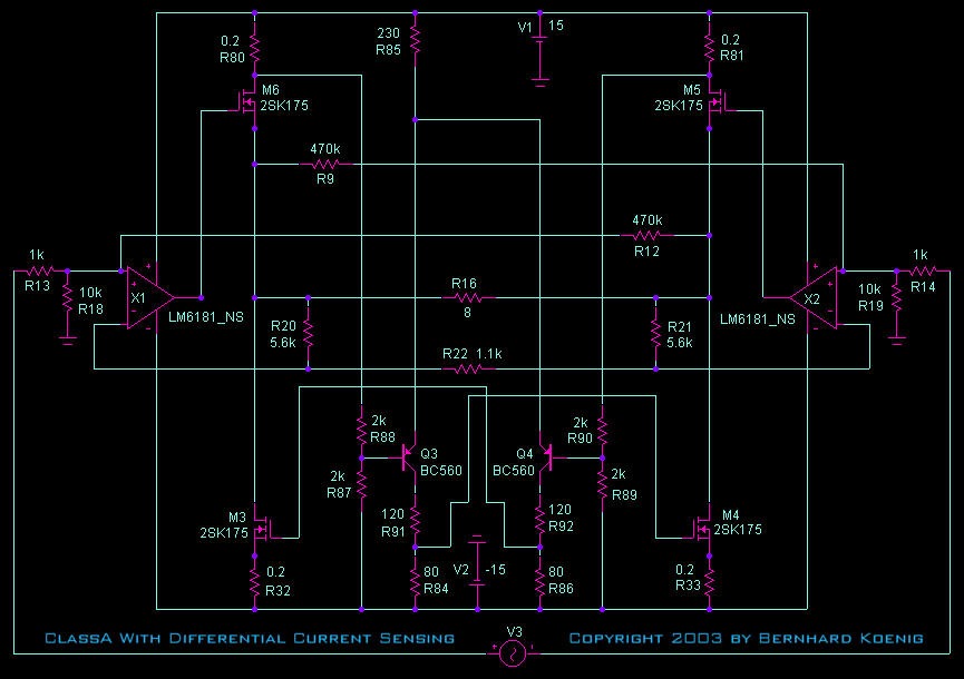
On this website I found a more simple circuit with the current sensing via cap...
Quote:
This is an extremely useful and trouble-free form of push-pull output; I have used it many times in preamplifiers, mixers, etc.
Greetings, Bernhard
thanks, this explanation could help me to understand, just need some time...
Another thing about the question if this is single ended or push-pull:
On this website I found a more simple circuit with the current sensing via cap...
Quote:
This is an extremely useful and trouble-free form of push-pull output; I have used it many times in preamplifiers, mixers, etc.
Greetings, Bernhard
Bernhard,
This technique is used in many forms. A boostrap is related to it, as is the grid drive on a White Cathode Follower, a tube circuit of astonishing performance. A capacitor is used to convey a voltage pulse arising out of a change in current - a 'current sense coupler'.
The system I explained, and Doug Self also, is in truth Single Ended. It's implementation leads logically to the Single Ended Push Pull with Sliding Bias, which I am working on at present. This circuit holds huge promise, in my view, because it has sufficiently low output impedance (without global negative feedback) to drive speakers directly, is extremely accurate, and can be made moderately efficient (around 40%) whilst delivering all the benefits of a non-switching Class A output stage. Add to that its H2 distortion only, nothing more, and you have the nearest thing to a high power SET I've ever seen.....
Cheers,
Hugh
Hugh,
just looking on the left side (not bridged) does that produce 2nd or 3rd order harmonics ? 😕
It is my alternative circuit with much less idle consumption, my active speakers need 8 amps
Greetings, Bernhard
just looking on the left side (not bridged) does that produce 2nd or 3rd order harmonics ? 😕
It is my alternative circuit with much less idle consumption, my active speakers need 8 amps
Greetings, Bernhard
Ok, I understand the single ended thing.
If we look at the left side, the upper Fet (master) dictates the voltage and the lower Fet (slave) carries the current at all times.
When the sine is positive, the slave carries less current, so less energy is wasted.
When the sine is negative, the slave carries more current, because the master can not deliver it.
But, now what bad thing might happen if the master tells the slave about his own voltage and not about his own current and if we have an evil load ? 
If we look at the left side, the upper Fet (master) dictates the voltage and the lower Fet (slave) carries the current at all times.
When the sine is positive, the slave carries less current, so less energy is wasted.
When the sine is negative, the slave carries more current, because the master can not deliver it.
But, now what bad thing
might happen if the master tells the slave about his own voltage and not about his own current and if we have an evil load ? 
- Status
- Not open for further replies.
- Home
- Amplifiers
- Pass Labs
- X = bridged = push pull ? ...