Mr Pass, don't forget that you can make them real shinny when pollished 😀
And for the EMI people, its a shielded transistor.🙄
Usualy when mounting TO220 or similar i prefer to use the metal fin to supply power. So not the pin. I feel the pin's are mostly to thin (especially the lower piece of the pin) for the given currents. The TO3 pins are better in that respect.
You'll never get around mechanical connections, when the currents are high and the copper parts are really heavy, soldering is a very unreliable method because you can never heat all the copper to make a good joint. (unless you want to use a blowtorch inside your amp). And a lot of big Caps are also screw-mounted
Peterpan188, i've checked my book, it does say like i posted before.
So
Id= K((Vgs-Vt)^2) (1+L* Vds) -> saturation note that (Vgd-Vt)^2 is negative so doesnt come in equation.
Id = K((Vgs-Vt)^2) - ((Vgd-Vt)^2)(1+L*Vds) -> linear
Your formula looks simular, so maybe just another type of aproximation of MOST behavior. Doesn't really matter, both non linear and that was the point i was trying to make.
Like Mr Pass said, its the question wich of the two evils you prefer. non linearity (distortion) or feedback (other distortions)
Jacques
I've never seen a pin for an output device melt--the little wires inside go first. And certainly not in normal use. Any resistance the leads might add is mitigated by the fact that they're quite short. It's really pretty much of a non-issue.
No one has ever claimed that gain devices are linear. That's one of the reasons that the push-pull output concept works as well as it does--the two non-linear curves sum to create one that is really a pretty decent approximation of a straight line.
Given that the anomaly that Nelson is describing is pretty much centered around the Drain, it's not a big problem for follower applications.
Grey
DiMenSioN said:
Peterpan188, i've checked my book, it does say like i posted before.
So
Id= K((Vgs-Vt)^2) (1+L* Vds) -> saturation note that (Vgd-Vt)^2 is negative so doesnt come in equation.
Id = K((Vgs-Vt)^2) - ((Vgd-Vt)^2)(1+L*Vds) -> linear
Your formula looks simular, so maybe just another type of aproximation of MOST behavior. Doesn't really matter, both non linear and that was the point i was trying to make.
Like Mr Pass said, its the question wich of the two evils you prefer. non linearity (distortion) or feedback (other distortions)
Jacques
I think both my and your equations are ultimately the same sort of approximations for MOSFET. The problem lies not in which equation, but more about the nature of the equation.
In saturation mode,
Id= K((Vgs-Vt)^2) (1+L* Vds)
as you set your operating point on the graph with Vds and Id (assuming Vgs is constant), small signal voltage variation, vds, about Vds operating point will produce a large variation of drain current, id. Through a resistor or any other type of I-V conversion, you will give a large voltage swing, controlled by a small voltage swing. This is essentially how amplification works.
Now non-linearity is another story. Non-linearity refers to the fact that a small change of input voltage doesn't give a output voltage with the same amplification factor at all points. In the real world, a large resistance resistor is a almost-perfectly linear device, where the voltage input across the resistor will almost perfectly transfer as a output voltage across the resistor. This gives the amplification factor or gain, of 1, with of course some loss due to heat and noise. The non-linearity of a resistor is none, in the ideal world. A MOSFET in saturation does almost the same thing, as you can notice in the graph I attached before. In saturation, the I-V characteristic is almost exactly the same as a resistor. So the non-linearity is minimal, as opposed in triode where there is a second-order dependence.
Now, all about MOSFET are approximations, and the I-V characteristic in saturation isn't really as linear as we want, so there comes the non-linearity. It is not the approximation or the equations that present this linearity, it's the reality. If those equations we wrote are exact description, we would have never needed any sort of feedback or distortion-correction on non-linearity, because those imaginary devices are perfectly linear in saturation.
Peterpan188:
Two people saying the same thing, although you have put it down way better than me.
I was starting this because i thought that ZenMod didn't understand the non-linearity part of that point in my first post. He was however confused about the X / XA part.
My real point about this non linearity was that because no active device is linear i would like to use feedback over de last stage. But prefferably using feedback without giving the speakers a chance to feedback noise in the loop.
I'll post schematic of what i mean soon.
I think MOST's don't use tiny wires like chips on the inside. The pins run al the way to the N and P materials. You do have a point that they might melt first. But to give a funny example: IRF1404, continuous drain current (100degrees): 143A, peak current: 808A. I do feel that those pins are not up to those kind of currents. It says somewhere in the datasheet that package limitation is 75amp, still a lot for the thin part of the pin.
About the push pull configuration. Lets say amplication is perfect at voltage X (bias voltage). Above voltage X amplification is a little to low, and below X amplification is a little to high.
Asume amplifying a sinus wave, upper most is above voltage X, lower MOST is below voltage X. So upper most conducts a bit less current then ideal and the lower most conducts a little to much. The output voltage will be a litlle lower than it should. Around X the device is at its best linearity and so a very small sinus is almost perfectly reproduced. The higher the amplification, the more error and the more the output sinus is not how it should be.
I'm not sure where push-pull is helping reduce this distortion.
Two people saying the same thing, although you have put it down way better than me.
I was starting this because i thought that ZenMod didn't understand the non-linearity part of that point in my first post. He was however confused about the X / XA part.
My real point about this non linearity was that because no active device is linear i would like to use feedback over de last stage. But prefferably using feedback without giving the speakers a chance to feedback noise in the loop.
I'll post schematic of what i mean soon.
I've never seen a pin for an output device melt--the little wires inside go first. And certainly not in normal use. Any resistance the leads might add is mitigated by the fact that they're quite short. It's really pretty much of a non-issue.
I think MOST's don't use tiny wires like chips on the inside. The pins run al the way to the N and P materials. You do have a point that they might melt first. But to give a funny example: IRF1404, continuous drain current (100degrees): 143A, peak current: 808A. I do feel that those pins are not up to those kind of currents. It says somewhere in the datasheet that package limitation is 75amp, still a lot for the thin part of the pin.
About the push pull configuration. Lets say amplication is perfect at voltage X (bias voltage). Above voltage X amplification is a little to low, and below X amplification is a little to high.
Asume amplifying a sinus wave, upper most is above voltage X, lower MOST is below voltage X. So upper most conducts a bit less current then ideal and the lower most conducts a little to much. The output voltage will be a litlle lower than it should. Around X the device is at its best linearity and so a very small sinus is almost perfectly reproduced. The higher the amplification, the more error and the more the output sinus is not how it should be.
I'm not sure where push-pull is helping reduce this distortion.
You're missing a number of things, but as I'm tied up with the kids at the moment, I'll just give a couple of hints:
--Resistance is proportional to the length of the conductor. Shorter length means less resistance means less heating means the lead can take the current
--Peak current by definition means short duration which means less heating (something shown explicitly in the SOA chart for a given device)
--Find a chart which graphically shows the resulting curve for a push-pull output stage.
Grey
DiMenSioN said:I'm not sure where push-pull is helping reduce this distortion.
If they (P&N) have the same transconductance charaters,
the net sum of the push-pull results would see symmetry swing.
But, there would be 3rd harmonic distortion.
It they have well-controlled matching transconductance curves.
the distortion could be less or very small. Our effort on this matching
would be rewarded, I think.

Thanks for the hints Grey, you are right. (if i may adress you with your first name)
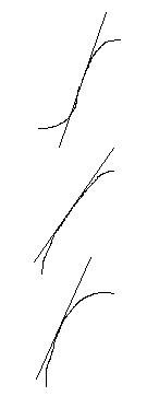
If the tangent line through the point were the bias is, lies above the actual amplification curve and the curve is symetric around this bias point then the push-pull units do cancel eachothers non-linearity out. (second drawing)
If however the amplification curve is above the tangent line below bias point and below the tangent line above the bias point then the pushpull topogoly makes the nonlinearity twice as bad. (first figure)
If the curve below the tangent line is not symetric the non-linearity doesnt cancel out (totally). (last figure)
All this is only vallid when the push and the pull device have the same curve.
So you need to have a push and a pull device with the same curve AND you have to choose the bias point so that the curve is symetric around the bias point and the tangent line of the bias point has to be above the amplification curve for the working area.
Sorry for the crappy paint-art 😉
Now the questions is. At what bias do these two conditions satisfy for the IRFP240 and IRFP9240?
Oh, i checked on the diodes, they are BYW51-200. They are fast lowdrop diodes. Didn't see any slow recovery in datasheet. Use them or use the slow standard 35A metal bridge rectifiers? On fast diodes, should you use MKP/MKT 100nf in paralel?
Jacques
Attachments
- Status
- Not open for further replies.
- Home
- Amplifiers
- Pass Labs
- X amp considerations