Hello Bill,
You do not need to match the BD139 and BD140. The BD140 is operating as a common emitter amplifier and the BD139 is the collector load for the BD140.
😊
You do not need to match the BD139 and BD140. The BD140 is operating as a common emitter amplifier and the BD139 is the collector load for the BD140.
😊
The BOM has just been updated - thanks for catching that!@Bonsai
If I'm not mistaken, there may be a small error in the current BOM for the PSU:
The BOM "X-Altra-Mini-II-BOM-October-2022 (1) (1)" on the site refers to MSR 532-532702B02500G but the footprint refers to 532-529802B025G or 532-529002B025G which should be read as: 532-529802B02500G or 532-529902B02500G
To me, the ref from the BOM would not fit in the footprint used on the latest PSU board.
Thanks,
Raph

Update on Remote control X-Altra Mini II front plate: the new IR Plexiglas window should arrive this coming week. I will assemble it, photograph it and then Gianluca will show it with the other non-Remote X-Altra Mini II front plate. You should be able to order a remote housing kit from late next week.
Concerning C18,C19 forget about it, I didn't think enough I guess as they are common to both the OPA1641 where they are placed. Right?@Bonsai in the RIAA MM/MC schematic and BOM, shouldn't R5(150R Right channel) and R6(330R Left channel) be of the same values? If yes, which one is the right one?
And, is it normal that we have C18,19 (1uF 50V) only on the right channel?
Sorry for the noise if I'm wrong.
Thanks.
I'll wait for you on the R5,R6 question though.
Many thanks.
Thanks for catching another one!@Bonsai in the RIAA MM/MC schematic and BOM, shouldn't R5(150R Right channel) and R6(330R Left channel) be of the same values? If yes, which one is the right one?
And, is it normal that we have C18,19 (1uF 50V) only on the right channel?
Sorry for the noise if I'm wrong.
Thanks.
R5 and R6 must both be 330 Ohms - I'll post an updated schema and BOM tomorrow.
C18 and C19 are shown on the right channel but because of the compact board size and the loacation of these caps, they are providing decoupling for both channels.
Appreciate your feedback - thank you!
🙂
@Bonsai, sorry for not grouping feedbacks, I'll do better next time.
As you will update the BOM of RIAA:
R1,R30,R34 are listed as 150 (just like in schematic) and have ref 603-RT1206FRE07270RL which is 270,
R2 is listed as 150 (just like in schematic) and have ref 603-RT1206FRE07270L (which is 270 with a typo).
If they are R150, we should read MSR 603-RT1206FRE07150RL just like R11,R18,R28,R29.
R38 has REF 603-RT1MEG, it should be the same as R37: MSR 603-RT1206FRE071ML
This one is just to be sure: R25,R26,R31,R35 are listed as 68k, the REF is 652-CRT1206FZ6812ELF which is 68.1k which is ok as it is in the 1% tolerance of 68k, if we really want 68k at 1% Yageo has 603-RT1206FRD0768KL.
Thanks
Here are some pictures of the final X-Altra Mini II Remote Control. The complete kit for the housing will be available on the modushop website shortly. I will add the link to the first post once it is available. The red LED at the top position of the volume control is the mute function - when the pre is muted, the LED illuminates between the front panel and volume control knob gap. It’s completely hidden from sight otherwise.

Last edited:
Very nice. The HP sockets insert is a little bit off center. How the socket fixed to front panel?
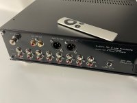
Finally, one of the rear panel. The Remote Control board also provides a +12 V trigger output (40 mA max with current limiting).
View attachment 1107151
You can move the headphone socket board around by c 1 mm for better alignment. The board screws into back of the front panel in a recess with 2 off M3 X 6mm screws.
View attachment 1107151
Very nice. The HP sockets insert is a little bit off center. How the socket fixed to front panel?
You can move the headphone socket board around by c 1 mm for better alignment. The board screws into back of the front panel in a recess with 2 off M3 X 6mm screws.
Gianluca at Modushop has put the new Remote Control X-Altra-Mini II Chassis up - you can buy them now
https://modushop.biz/site/index.php?route=product/search&search=XALTRA
These are beautifully made and come with:-
Housing with metal covers (for better screening) side plates
Machined and laser printed front panel
Blank 3mm aluminium base plate (you drill the holes to mount the board using the template linked to in the first post)
No rear panel - this is suppled from my side as a double PCB pair, drilled, milled and printed.
On the Remote Control version, a Plexiglas insert is provided that slots into the square milled hole - secure in place with a small dab of clear RTV in each corner
🙂
Nothing - Modushop are supplying direct. I just sell the PCB’s and provide any support for builders. This is DIY 🙂
(my commercial stuff is kept completely separate from here)
(my commercial stuff is kept completely separate from here)
👍👍😁😁😁@Bonsai,
We really appreciate how much you indulge us with your engineering prowess. Thank you!
Best,
Anand.
- Home
- Source & Line
- Analog Line Level
- X-Altra Line Level Preamp