That seems a bit on the low side. When you power the unit on, is there 120VAC from switch load to neutral?
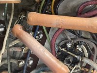
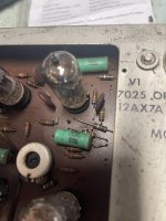
Hi so I misunderstood the jumping out the relay and it equating to jumping out the two connections on the receptacle. After making two jumpers for the receptacle the unit powered on with a strong hum. One of these large resistors got very hot at 40 volts and at 50 volts the 5amp fuse on the variac blew. Also all tubes lit up (which I know dosent show condition) except the top half of one 12ax7a tube only bottom half of this tube lit up. Thanks so much for your help gain
Guy
Guy
Attachments
You have a short circuit somewhere.
Where are the hot resistors on the schematic?
Which tube did not fully light up as it is shown on the schematic? Is it V1?
Where are the hot resistors on the schematic?
Which tube did not fully light up as it is shown on the schematic? Is it V1?
Well, you might examine the filament wiring around V1 to make sure it is properly intact. Also inspect the socket for any signs of arcing, burning, bad connection, etc. Also remove V1 from its socket and measure the resistance of the filaments. Also measure for any short to the cathode. Maybe best if you have a tube tester or else a substitute tube.
Whatever is drawing too much current through the 310R resistor must be found, if that's what caused fuses to blow. Could be a shorted electrolytic cap from bringing up the voltage too fast without monitoring the current draw carefully enough.
Whatever is drawing too much current through the 310R resistor must be found, if that's what caused fuses to blow. Could be a shorted electrolytic cap from bringing up the voltage too fast without monitoring the current draw carefully enough.
Hi I swapped all tubes from channel a to channel b. The same resistor still gets hot so I’m guessing it’s not the tubes and tube soccers look clean. Thank you
The resistor and its common resistor on the other channel are both within spec one goes straight to chassis ground. The other goes to speaker common then chassis ground
Can you draw a circle around the hot resistor on the schematic so we can see which one it is functionally? One of the cathode resistors for the output tubes?
Maybe an output tube is shorted? Maybe its grid is driven positive because of a shorted grid coupling cap?
Maybe an output tube is shorted? Maybe its grid is driven positive because of a shorted grid coupling cap?
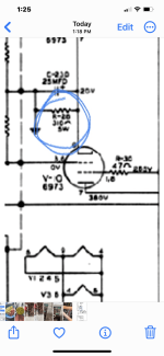
Is it the resistor outlined in red below?

Are either of the caps outlined in orange shorted?
You need to be VERY careful in this area if measuring anything with power on. There is close to 400v on the output tube anodes. Your meter and test leads may only be good for 600V max. Best to check. Best to plan and practice any measurements with the power off.
Also, do you have any experience with measuring high voltages? It may be getting close to time to get some help or go to a repair shop.
If you intend to keep going you may also need an oscilloscope soon to see what is going on. Maybe another reason to go to a repair shop.
Hi I removed the two capacitors from circuit and they tested within their generous tolerance of 20%. I’m hoping you have other suggestions.
Regards
Guy
Regards
Guy
Check the resistors shown in the schematic as just to the right of the caps in orange boxes. They are the power tube grid resistors. Something is causing one or both tubes to be pulling too much current. At least, that would be suggested if the 5W resistor is getting more hot than it should. You could also measure the voltage drop across the 5W cathode resistor, but that's a power-on measurement in an area where there would be high voltage on some of the tube pins and adjacent components.
Or maybe you could try pulling the power tube and then see if the amplifier still blows fuses with the tube removed.
Also, always remember that when you turn of the power there is still high voltage present until the capacitors discharge. You need to know what you're doing in terms of safety when working on something like this.
http://tubelab.com/safety/
https://robrobinette.com/Tube_Amp_Safety.htm
Hello Gentlemen, I’m making progress on the amplifier and am learning a lot along the way. There was a short and it was one that I created. I thought the socket PIN numbers ran clockwise from the top of the chassis only to learn that it was the under side of the socket.
The suggestion to buy a variac most certainly saved the amp as the variac fuse was blowing.
Next the amplifier powered on and there’s was a pronounce hum. I changed the power supply capacitors and left the cans placing them under the chasis. Also jumped the relay for the remote turn on. Thank you all for walking me through.
If you’re still reading I do have some new questions. The output is very low I am curious what voltage input this amplifier is designed for.
My Regards Guycom
Also, did you figure out how the built-in volume control works? If so, do you think its working right? Do you have signal generator or sound card?
Hi, No scope yet I don’t know how to use one. The amplifier is working so well what I thought was loudness contour was a loudness adjustment. I guess that’s just something else I need to learn,a lot of volume no hum or hiss very happy with the way it came out, thanks again for everyone’s help
Attachments
Hi and thank you for any help. Yesterday I cleaned the volume and balance pots and listened to the amplifier for hours. Today I get no audio. If I tap the output tubes or move the tone controls I hear it produce a noise at speakers. The two wax caps at the input rca’s may have smoked a bit as it was very hard to see where it came from. I am going to change them as I know these are problematic. Anything else I should look for ? Do these caps often go bad at start up? Input device is a Bluetooth adapter.
Thank you. Guycom
Thank you. Guycom
- Home
- Amplifiers
- Tubes / Valves
- Wurlitzer 543 amplifier questions