Hello and thank you for any help. I would like to bench test my 1962 Wurlitzer 543 amplifier from a 2600 juke box.
What jumpers do I need to make to bench test the unit ?
What speaker output terminal screws would be best for a pair of 8ohm speakers?
Thank you
Guycom
What jumpers do I need to make to bench test the unit ?
What speaker output terminal screws would be best for a pair of 8ohm speakers?
Thank you
Guycom
Do you have a schematic?
EDIT: Found the service manual.
EDIT: Found the service manual.
Attachments
Last edited:
Wow. Thank you it’s more than I thought available and what little I found was illegible.
I think it is described as a muting plug on the schematic. There’s a double throw relay would that need jumping to bench test ?
Thank you very much
I think it is described as a muting plug on the schematic. There’s a double throw relay would that need jumping to bench test ?
Thank you very much
Yeah, looks like there can be a muting plug which if not plugged in, should not mute. Also relay RY in the power supply area that may need a terminal strip jumper.
Looks like the volume control is tapped to allow for equal loudness contour compensation (more bass at low volume levels). Rough volume level is selected by the speaker tap in use, IIUC.
Looks like the volume control is tapped to allow for equal loudness contour compensation (more bass at low volume levels). Rough volume level is selected by the speaker tap in use, IIUC.
Hello , and thank you again for your help.
I have found relay R Y and I can put a terminal strip to jump all contacts that are made in the relays powered state.
The mute socket will remain empty.
I would like to install a 3 wire plug and run the ground to the outer casing if you feel that advisable.
Regards Guy
I have found relay R Y and I can put a terminal strip to jump all contacts that are made in the relays powered state.
The mute socket will remain empty.
I would like to install a 3 wire plug and run the ground to the outer casing if you feel that advisable.
Regards Guy
Looks like the lead that goes to F5 would be the AC line hot....install a 3 wire plug and run the ground to the outer casing...
The AC line input shown on the schematic would Neutral.
Looks like AC line ground could be connected to chassis.
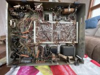
Also looks like there might be a long terminal strip on the left in your pic to jumper RY in the on state already.
If it hasn't been powered up for a long time, you might want to try bringing up very slowly with a Variac, while watching the current. Some caps may need some time to slowly re-form.
Last edited:
Thank you. I’m going to make a lightbulb voltage reducer as I don’t have a variac. Ac line first. I’ll keep you informed on my progress.
Guy
Guy
Maybe good to start with a pretty small wattage lightbulb first in that case. Perhaps a night light bulb, 3 or 7.5W, or whatever you can find. If you can't get enough control over the voltage rise across the caps you might try pulling some tubes from the amp so that filament current doesn't dominate the drop across the series bulb. As you start to get up closer to normal voltages then replace tubes and use a higher wattage bulb.
Between the two things you have control over, bulb and tube loads, the idea is still to watch the current draw, let it stabilize at each step while also keeping an eye on B+ levels so you know that the caps are holding. Same as you would try to do if you had a variac.
Also, do you have a scope to check for ripple? If not you can sorta measure that with a DVM set to AC volts (read the DVM manual first to see how much DC its rated for without a special HV probe). If a cap has lost too much of its uf value, you might see more than normal ripple.
EDIT: If you're not used to working with tubes and or HV, its good practice to decide what points you want to measure with the power off and the caps discharged. Practice how you will place the probes without causing an accidental short somehow. Or else hook up the probes before you power on. Its just that randomly poking around with HV on can have bad consequences. I know of a guy who let a scope ground lead drop and touch a HV point on a 400A, 350VDC power supply. Pretty much evaporated the grounds on all the PCBs in an expensive-at-the-time 100Mhz Tek scope. Totally destroyed it.
Last edited:
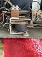
Hello, sorry for the delay I was waiting for my variant to come. Surprisingly inexpensive $40 shipped. The amplifier did not power up noticed that the relay that I had jumped as I like going to a gang connector and I took a picture of the connector and made an arrow to show where the wires landed underneath. Thanks again for your help. Looking forward to hearing from you, Guy
Attachments
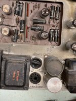
Sorry for the typos. Variac of coarse and the bypassed relay leg goes to the arrow marked connection in the gang connector
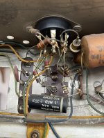
That socket appears to be the thing outlined in red below:

Dotted lines show where the jumpers would go. Do you know how to count pins on a tube socket? Looks like they may be counting clockwise from the top, starting at the alignment notch. That's backwards from normal tube socket numbering, which should be clockwise as viewed from the bottom.
Dotted lines show where the jumpers would go. Do you know how to count pins on a tube socket? Looks like they may be counting clockwise from the top, starting at the alignment notch. That's backwards from normal tube socket numbering, which should be clockwise as viewed from the bottom.
Hi. I have one and 5 jumped at relay and 3 and six jumped at female connector in chassis 120 volts thrue fuse and switch to neutral. I’m not getting any signs of paneer at tube and transformers are cold. I also double checked all fuses and they’re good.
Thank you for your help. Guy
Thank you for your help. Guy
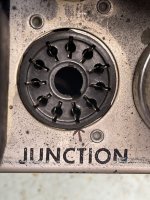
Do you have a multimeter? Do you have lightbulb or other device connected in series with amplifier power? Do you know how to read the schematic? Does RY close? If not, does it have any AC or DC voltage across the coil? Is there 120VAC across the socket labeled "lights?"
If you unplug the amplifier from AC power, turn on its power switch, and measure resistance across the AC plug, do you see any resistance there or is it infinite?
If you unplug the amplifier from AC power, turn on its power switch, and measure resistance across the AC plug, do you see any resistance there or is it infinite?
Last edited:
Hi yes I have a multi meter and the relay is bypassed I have the amplifier attached to a recently purchased variac
Thank you
Thank you
Also, it looks like RY runs on DC power. It probably won't close unless a jumper is placed across where the dotted lines are in the red box below:

Ok, then measure the resistance at the AC plug. You should see the resistance of the power transformer primaries from there if switch, fuse, and wiring is all intact.
NOTE: Also FYI, when testing with power on, it looks like the tube filaments are biased a some high-ish DC voltage above ground, so be careful around the filament wiring, etc.
NOTE: Also FYI, when testing with power on, it looks like the tube filaments are biased a some high-ish DC voltage above ground, so be careful around the filament wiring, etc.
Hi Ty is jumped out and taken off relay. Thank you for the warning on the high voltage. I will check for resistance to ground at switch load. Report back soon
Guy
Guy
- Home
- Amplifiers
- Tubes / Valves
- Wurlitzer 543 amplifier questions