F4 PCB wiki want list started
I have started a Wiki for some reissue of Peter Daniels PCB's of Firstwatt F3 and F4 boards. If your interested please visit the below link. I beleive 50 stereo sets of each are needed for a minimum production run. Please edit the Wiki carefully.
http://www.diyaudio.com/wiki/index.php?page=FirstWattPCBReissues
🙂
I don't know how to use that wiki. What a stupid old man I am. Anyway I'd like to have 4 PSU 2 F3 and 2 F4
F3 AND F4 BOARDS WIKI
Luvdunhill,
I added the thread to the PIC layouts to the wiki.
On page 2 I beleive is the Zen v9 variation. I am not sure of the differences here between Z9 and F3 boards, if any. Possible PD can elaborate. I dont want to float to OT here.
Here is a link to the F3 PCB pic
http://www.diyaudio.com/forums/showthread.php?postid=1298349#post1298349
Here is a link to the F4 PCB pic and power supply.
http://www.diyaudio.com/forums/showthread.php?postid=1230598#post1230598
🙂
Zv9 were single sided with less capacitors onboard: http://www.diyaudio.com/forums/showthread.php?postid=968617#post968617
If my cost is the same as last time, the prices will be as listed here: http://www.diyaudio.com/forums/showthread.php?postid=1298371#post1298371
But that also depends how many amp boards are ordered, last time it was 150 or so.
But that also depends how many amp boards are ordered, last time it was 150 or so.
Ok, I'm gathering parts for an F4 , just found this interesting thread.
Is Peter still taking orders for any F4 signal ( amp ) boards ?
If so, can someone link me back to a pic of the amp board, I can only find the PS PCBs so far !
I need to see what the shape/length is before I order some heatsinks .
Thanks in advance .
MJ
Is Peter still taking orders for any F4 signal ( amp ) boards ?
If so, can someone link me back to a pic of the amp board, I can only find the PS PCBs so far !
I need to see what the shape/length is before I order some heatsinks .
Thanks in advance .
MJ
IslandPink said:Ok, I'm gathering parts for an F4 , just found this interesting thread.
Is Peter still taking orders for any F4 signal ( amp ) boards ?
If so, can someone link me back to a pic of the amp board, I can only find the PS PCBs so far !
I need to see what the shape/length is before I order some heatsinks .
F4 amp boards are still available, the info was posted here: http://www.diyaudio.com/forums/showthread.php?postid=1680605#post1680605
I've gathered parts for a stereo F4 I won't build...
2 x IRFP240 and IRFP9240 Matched Triplet Sets
2 x 2SK170BL
2 x 2SJ74BL
2 x TL431
PM if you're interested
2 x IRFP240 and IRFP9240 Matched Triplet Sets
2 x 2SK170BL
2 x 2SJ74BL
2 x TL431
PM if you're interested
Thanks for the responses chaps.
I will take up the offers of the two guys who seem to have parts they don't need.
I will try the PM facility first but it may not work for me straight-off ; someone tried to PM me recently and it wasn't working .
If not I will post an email on here in some form .
Monsieur Korben69, you have Mosfets & Fets , do you have boards also ?
Thanks
MJ
Power jFets
Big thanks to Korben69 who traded some Lovotech jFets to me. I live in Santa Clara where Lovoltech is...and my jFets came all the way from France. I'm glad that F3 stumbling block is out of the way
Regards,
Chris
Big thanks to Korben69 who traded some Lovotech jFets to me. I live in Santa Clara where Lovoltech is...and my jFets came all the way from France. I'm glad that F3 stumbling block is out of the way
Regards,
Chris
You're welcome Chris 😉
Nice to see that LU1014D have landed safely and will make a F3 alive !
No more LU left from Grey ROLLINS Eu GB (thanks to him for this).
I've got two F4 sets for sale, they are pending...
Nice to see that LU1014D have landed safely and will make a F3 alive !
No more LU left from Grey ROLLINS Eu GB (thanks to him for this).
I've got two F4 sets for sale, they are pending...
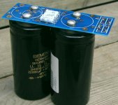
I'm intrigued by the possiblity of using some large 'screw-mount' caps on the PSU board. I'm assuming I'll have to drill my own holes.
Any words of caution???
And, do any traces on the bottom need to be cut???
I've attached an image from earlier in the thread to show what I'm talking about...
Please excuse all my dumb-noobie questions.
Thanks,
Any words of caution???
And, do any traces on the bottom need to be cut???
I've attached an image from earlier in the thread to show what I'm talking about...
Please excuse all my dumb-noobie questions.
Thanks,
Attachments
R24/R25
Wow, doesn't time fly ?
I now have heatsinks and I'm just getting the remaining parts I need to fill the PCBs .
Reading back through the thread, I understand the purpose of the extra C5-C6 on Peter's boards, to put the final part of the PS on-board with the signal section - that's fine. However, I can't find any info on items R24 and R25 in discussion, or in the BOM pdfs. Unfortunately the link to the 'other' circuit diagram which includes C5 C6 etc is now not working .
I expect that R24 R25 are not critical, but would still appreciate if anyone could fill me in on the details .
Also, if there is a link to show conventions of orientation on three-legged devices , I'd appreciate it, coming from the valve ( tube ) world ! I can see a double line on the mosfet outline and I assume it represents the back/mounting flange ; not sure about Q1/Q2/Q11...
Thanks in advance if anyone is out there .
Mark
- Status
- Not open for further replies.