Payment sent!
Thanks again, Ron
Thanks Ron,
I have received it will ship your boards on Monday and provide you tracking no.
Regards,
Sachin
PM me with transaction details at your convenience.
Regards:Csaba
Did you receive my PM?
Regards,
Sachin
PCBs received
Received PCbs today posting a pic :
Thanks Rudi
Regards,
Sachin
Received PCbs today posting a pic :
Thanks Rudi
An externally hosted image should be here but it was not working when we last tested it.
Regards,
Sachin
Last edited:
Well done, Sachin, I appreciate very much!
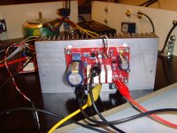
This is how the PCB shall eventually look like (see attached image).
I use Nichicon Gold / 10 µF for C3, MPC7x 5W resistors and a DELL PA10 / 19.5VAC - 4.6A LAPTOP PSU.
I am wishing you and everybody else a successful build - enjoy - Rudi
This is how the PCB shall eventually look like (see attached image).
I use Nichicon Gold / 10 µF for C3, MPC7x 5W resistors and a DELL PA10 / 19.5VAC - 4.6A LAPTOP PSU.
I am wishing you and everybody else a successful build - enjoy - Rudi
Attachments
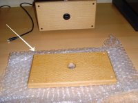
In case that anyone of you will use the same heatsinks, ..., that I used for my ACA#1: I will offer him
my spare wooden front - plate for 1€ + 3.45€ (world-wide shipping).
P.S.: Yes: I am a carpenter (LoL) 🙂 and you will never again have a such pretty front-plate like this one.
my spare wooden front - plate for 1€ + 3.45€ (world-wide shipping).
P.S.: Yes: I am a carpenter (LoL) 🙂 and you will never again have a such pretty front-plate like this one.
Attachments
Last edited:
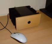
I forgot to add this picture.
Tarzan: it is me, Jane! :
Best regards -You_Tarzan - Me_Jane
Tarzan: it is me, Jane! :
Best regards -You_Tarzan - Me_Jane
Attachments
Last edited:
Yes really nice piece of wood you have there. I plan on monoblocks and using 2 aluminum lawnmower heads for heatsinks. Might use motorcycle heads since ACA is intended to replace my garage system one day. But things have been known to change...
Dear Sachu!
Yesterday the PCB's are received - Nice work!
Thanks !
Csaba
Hi Csaba
Thanks for confirmation.
Regards,
Sachin
Sachin, find attached the Gerber files and the schematics that I have used.
The PCB is single-sided; the layout is proven and completely routed.
I am using MPC74-type resistors as "drain/source" resistors.
Please offer your PCBs to MeTarzan-YouJane, to MORTRON, to ... as well.
Best regards - Rudi_Ratlos
This schimantic is little different from the original circuit diagram. I am having this PCB now.
Here the top end of the pot is connected to output capacitor and meeting point of R1, R2 , R3, R4 and not connecting to ztx450 at all. But in original circuit, it is connected to meet R3,R4 and emitter of ztx450.
I was looking to add 6w mod of 2.21k resrstor but found this PCB not in line with the original circuit and got confused.
Please help.
Its more than a year since previous post! has anyone built this version of ACA as per post #9 ??
More than 30 builds as far as I know.The amp is very good, thanks to Rudy.
I now have Discrete Dynamic power amp modules FS: Discrete Dynamics Class A/B Power Amp modules
Regards
Sachin
I now have Discrete Dynamic power amp modules FS: Discrete Dynamics Class A/B Power Amp modules
Regards
Sachin
@Rudi_Ratlos
Could you possibly tell me pls, based on your schematic, what is the max voltage this amplifeir would be able to handle? Im planning on etching my own boards using the iron on method. I already have the prints done and will be etching this evening. Im just having a problem finding a power supply to run two of these modules in one chassis.
PS: thank you for the effort you put in, this is exactly what I wanted.
Cedric
Sachin, find attached the Gerber files and the schematics that I have used.
The PCB is single-sided; the layout is proven and completely routed.
I am using MPC74-type resistors as "drain/source" resistors.
Please offer your PCBs to MeTarzan-YouJane, to MORTRON, to ... as well.
Best regards - Rudi_Ratlos
Hi guys
What program to use to open the Gerber files? And if I do the etching, then so I have to mirror this image still
The Gerber-files above include a modification to reflect the correct orientation of the ZTX450 on the silkscreen.
Best regards - Rudi_Ratlos