OOPS yes the negative rail do have the caps in wrong polarity.
About the D1 and D2 I meant to put them in the wrong direction, so the power goes trough the inductiors but let power run back when power is shut off, to avoid high kick back voltage.
Hmm yes the voltage drop is very high, but is it worth it? I am thinking more stable DC gives better "working condition" for the amplifier?
I did experiment with the FET bridge and have not tried it before, pleas tell the "story" 🙂
Thanks to Mooly did I find an error where Q8 were wrongly placed and I "stole" his configuration of the LT Spice schematic.
Since I am a noob I am of cause stumbled upon an thing I do not understand.
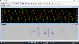
When the load is a 40 Ohm resistor, the Voltage output is nearly 45 +/- 200uV p/p, but if I replace the resistor with a LED 45V 10A, the output drops to 40V +/- 300uV p/p.
Why that voltage drop?
Since I am a noob I am of cause stumbled upon an thing I do not understand.
When the load is a 40 Ohm resistor, the Voltage output is nearly 45 +/- 200uV p/p, but if I replace the resistor with a LED 45V 10A, the output drops to 40V +/- 300uV p/p.
Why that voltage drop?
Attachments
You can't just place an LED across a voltage source because LED's are not really voltage driven but current driven. This means it will effectively load the supply very heavily. A real LED would just get hot and fail, the LT model might not reflect reality under those conditions.
This shows an LED pulling the supply down to 17 volts, but look at the current on the right hand scale 😉
The FET bridge as you have it drawn is relying on the parasitic diodes within each FET. These are an unavoidable artefact of the manufacturing process and are not really intended to be used as rectifiers.
Some bjt devices do actually have intended reverse biased diodes across C and E and these were often found in line output stages of old TV's and the like where they handled and clamped the high energy negative going flyback pulse from the LOPTX (line output transformer).
Just use ordinary diodes for the PSU plus a snubber either across each diode or a single snubber across each secondary winding. Use something like a 0.1uF 250V film cap and a series 2.2 ohm 1 watt metal or carbon film resistor.
Attachments
Sorry my late answer, I do not know why but I do no longer get a message when someone do reply to this thread, even that I have asked the forum to do it again.
Thanks for your great reply, my reason for wanting to use mosfets were to avoid the voltage drop. I have read about using the LT4320 chip to reduce the voltage drop and heat by about 90 percent. Since I do understand that heat in an amplifier is something you shall strive to reduce. Also the posibility to mount heatsinks on the mosfets, did make me believe that it will prolong the circuits life, instead of hot diodes.
Thanks for your great reply, my reason for wanting to use mosfets were to avoid the voltage drop. I have read about using the LT4320 chip to reduce the voltage drop and heat by about 90 percent. Since I do understand that heat in an amplifier is something you shall strive to reduce. Also the posibility to mount heatsinks on the mosfets, did make me believe that it will prolong the circuits life, instead of hot diodes.
I can promise you that using the amp for normal music (as opposed to high power sine testing into low impedance loads) will generate minimal heat in the diode bridge. If the bridge is the common type that just bolts to the chassis then you won't even feel it warm up. Its a non problem.
The voltage rating of the LT4320 means the absolute maximum rail voltage for the amp would be -/+36 volts or lower. The chip would also need protecting against transients if it were already running close to its maximum rating.
Just stick with a conventional PSU would be my advice 🙂
The voltage rating of the LT4320 means the absolute maximum rail voltage for the amp would be -/+36 volts or lower. The chip would also need protecting against transients if it were already running close to its maximum rating.
Just stick with a conventional PSU would be my advice 🙂
Se that's why I love this forum! I try something and you teach me a lot all the time! 🙂
So would it be a fine idea to mount the diode bridge on the heatsink I'll use to the amplifiers mosfets, thinking of using one long on each side?
My goal is to use the amp on a set of 4 Ohm speakers. You write +/- 45V as input to the amp. What bridge specification / "name" would you recommend to search for?
I used a 35A 400V bridge which has massive surge ratings (and they are a common choice for amps like this). It just screws to the chassis... job done. You do need a good soldering iron though because those tabs will take a lot of the heat.
GBPC3504 ON Semiconductor / Fairchild | Mouser United Kingdom
This is the same sort of part in a PCB mount package:
KBU3504-G Comchip Technology | Mouser United Kingdom
The difference here is that this part would get hot under continuous sine testing of the amp but having said that these style of parts are used in (for example) the Arcam Solo which includes a 75+75 wrms amplifier. For normal music these are fine.
Thanks a lot, I'll use that. About the soldering iron, I own a Hakko 808 and an sort of soldering gun but should the 808 not be enough?
EDIT: Forgot to ask, isn't it easier to mount number two rectifier to the board and then to the case, a bit like a mosfet?
EDIT: Forgot to ask, isn't it easier to mount number two rectifier to the board and then to the case, a bit like a mosfet?
Last edited:
Although I always solder to the bridge, you can also use push on "Faston Connectors".
The PCB type can be clamped to a heatsink if you can devise a suitable method... but... if you are just using the amp normally then heat in the bridge is not a problem and the PCB type would be fine just PCB mounted. You should keep the leads fairly short and have as much copper print around the pins as possible as that helps conduct heat away.
The PCB type can be clamped to a heatsink if you can devise a suitable method... but... if you are just using the amp normally then heat in the bridge is not a problem and the PCB type would be fine just PCB mounted. You should keep the leads fairly short and have as much copper print around the pins as possible as that helps conduct heat away.
Or, if you like the chassis mount bridge, jump in the deep end and buy some female spade terminals and a crimping tool.
Also, (someone smarter than me, please weigh in here ..) I'm pretty sure the dual common-mode chokes arrangement would require dual secondaries and dual bridges. And it isn't really the best place to put one.
Still loving your enthusiasm!😉
Cheers
edit: oops -- Mooly beat me to it ..
Also, (someone smarter than me, please weigh in here ..) I'm pretty sure the dual common-mode chokes arrangement would require dual secondaries and dual bridges. And it isn't really the best place to put one.
Still loving your enthusiasm!😉
Cheers
edit: oops -- Mooly beat me to it ..
Thank you a lot for your word, but it's only because of you all, I feel a great joy learning this fantastic world! 🙂
I am wondering if it would be a good idea to buy all sorts of cheap ebay components, just to test with, to see what happens by doing this or that? Right now do I only rely on what little knowledge I have simulating in spice.
I am wondering if it would be a good idea to buy all sorts of cheap ebay components, just to test with, to see what happens by doing this or that? Right now do I only rely on what little knowledge I have simulating in spice.
Experimenting with parts is great for experience and learning. I spent many happy hours when I was young with plug in prototype boards and lots of various parts.
You can even build this amplifier in that way... it's how I developed the design at the beginning.
Oscillograms/Testing, and why layout matters.
You can even build this amplifier in that way... it's how I developed the design at the beginning.
Oscillograms/Testing, and why layout matters.
I'd be tempted to stick with reputable suppliers at first -- DigiKey, Mouser, Arrow, Farnell, etc. -- just so the lessons learned are true. I'll never forget, one of my first projects used a CD4034. Countless hours went down the drain while I tried everything I could think of, absolutely convinced that I was overlooking something significant. Eventually so much time had been wasted, the only reasonable solution was to completely redesign it without that part -- and it took something like one-eighth of the time!
Today such complicated, high-performance, high-quality parts are available at such reasonable prices, its hardly worth the risk of working with any that you might not have 100,00% confidence in.
Just my 2 cents.
Cheers
Today such complicated, high-performance, high-quality parts are available at such reasonable prices, its hardly worth the risk of working with any that you might not have 100,00% confidence in.
Just my 2 cents.
Cheers
I'd be tempted to stick with reputable suppliers at first -- DigiKey, Mouser, Arrow, Farnell, etc. -- just so the lessons learned are true. I'll never forget, one of my first projects used a CD4034. Countless hours went down the drain while I tried everything I could think of, absolutely convinced that I was overlooking something significant. Eventually so much time had been wasted, the only reasonable solution was to completely redesign it without that part -- in something like one-eighth of the time.
Today such complicated, high-performance, high-quality parts are available at such reasonable prices, its hardly worth the risk of working with any that you might not have 100,00% confidence in.
Just my 2 cents.
Cheers
I bought some 74HC4051's off ebay.
When I powered up my new pcb some modes were producing the wrong voltage. I hunted around the circuit blaming wrong resistors etc.
Just out of interest I swapped out the 4051 and the circuit started working.
Some 4051's werent working right in some modes.
Since then I dont bother with ebay or Chinese components as they arent worth the hassle.
On the other hand I pay about £8 for an AD9281 from RS and £2 from Ali Express and they work ok.
Its all just a bit of a lottery.
I kow that ebay components can be bad, but if I only think of using them to see if something work and then later buy from the good dealers. I won't mind blowing up some cheap ebay component for nearly nothing.
But what if it doesn't work... and then you are left wondering whether its because of the way you built it or whether it is because of suspect parts.
When you build my Lateral FET amp you should first test it without the FET's fitted. The DC conditions should all be correct at that point apart of course from the bias adjustment. It is all low current stuff and so it would need some pretty catastrophic errors or faults to blow up.
When you build my Lateral FET amp you should first test it without the FET's fitted. The DC conditions should all be correct at that point apart of course from the bias adjustment. It is all low current stuff and so it would need some pretty catastrophic errors or faults to blow up.
Yes I see what you mean, if I bought from i.e. ebay, I'd have to test every single component before using them and maybe the signalwould be different them by quallity components.
By the way, I know I have asked you before but am not sure I did understand it🙂
Your circuit shows +/- 45V input but you do also tell about it being a 50W amplifier. According to what I hope I know, would 45V give about 253W. Will you please try to spoon-feed me your explanation again? 🙂
By the way, I know I have asked you before but am not sure I did understand it🙂
Your circuit shows +/- 45V input but you do also tell about it being a 50W amplifier. According to what I hope I know, would 45V give about 253W. Will you please try to spoon-feed me your explanation again? 🙂
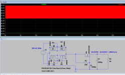
The voltage rails determine the maximum voltage that can be developed across the load.
So we start with -/+45 volts DC which means that a grounded load (the speaker or test resistor) could never see more than +45V or -45V across it at any given moment in time.
(The speaker can not see +45 at one end and -45 at the same time because it is a grounded load. It is one or the other).
So if a sine wave peaks at +45 volt at the top and -45 at the bottom we have a voltage across the speaker of -/+45 volts peak to peak or we can say a singular 45 volts peak.
Both are taken to mean the same thing.
So 45 volts peak multiplied by 0.707 gives a voltage of 31.8 volts and that is the rms voltage.
So we can deliver 31.8 volts rms to a load.
If the load is an 8 ohm resistor we get a power of (31.8*31.8)/8 which is 126.5 watts rms.
If the load is 4 ohm that doubles to 253 watts rms and so on.
The practical amplifier of course can not deliver that power because of a few limitations. One of the main ones is that the FET's have a relatively high 'on' resistance and so they 'loose' some of the 45 volts available across the FET, even when fully on. That reduces the available output quite a bit.
The simulation shows it clips at around -/+36 volts output when running into 8 ohm loading. That gives a power of (36*0.707)/8 which is 81 watts rms. I would say in practice you could say it is a 70 watt rms/8 ohm capable design.
The 0.707 multiplication factor is the same as saying divide by root 2 (which is 1.414)
This shows clipping point of the amp.
Attachments

WOW thanks! What a great and logical explanation and thanks for doing so much out of it.
I can see that my mistake were to think that you had a 90V span while it's in fact 2 x 45 peak to peak. And yes there are voltage drop and so on. But what about headroom, to avoid clipping when the music is hitting it's high points, as you greatly illustrates in your test result?
Am I right in thinking that if I chose to build the amplifier for 4 Ohm speakers, do I need 45V 6A or more?
- Home
- Design & Build
- Construction Tips
- Worst PCB track-layout ever?