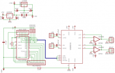
After taking a look at the new LM4562 from National I was mighty impressed by it's specs. I decided to design a board around it using the WM8816 from Wolfson to control the gain. I figure this is the next best thing to a stepped attenuator, but this also has the advantage of having a fixed input impedance.
The design itself is pretty basic. A PIC16F88 (love this chip) will be used to control the WM8816, which sets the gain of the LM4562. I have added headers for ICSP, auxiliary control of the WM8816, and the individual PIC ports for the connection of buttons, an IR Reciever, or an LCD etc. I still need to program the software for the PIC, so I will be working on that for the next little while.
What I am most interested in right now are some ways I can improve the design. If you have any constructive suggestions please fire away.
G. 🙂
Attachments
I've been looking to grow my PIC programming skills. The 16F88 looks like a great place to start. Can you recommend a good 'C' compiler and development system?
Carl_Huff said:I've been looking to grow my PIC programming skills. The 16F88 looks like a great place to start. Can you recommend a good 'C' compiler and development system?
Actually, I don't use C myself. I have been using Picbasic and Mikrobasic. You could take a look at this product http://www.mikroe.com/en/compilers/mikroc/pic/ if you are set on using C.
The PIC16F88 is indeed a very nice chip. It has nearly every feature you could ask for (well except USB...) and is in a nice sized package. The internal oscillator is a nice feature and also frees up two more pins for I/O options. I am by no means an expert at PIC programming, but I am competent enough to handle simple things like SPI. For programming my PIC I built this unit http://feng3.cool.ne.jp/en/pg5v2.html which I use with WinPIC. I also have a little JDM programmer with an ICSP header on it, you can find the details for that one here http://www.belza.cz/digital/jdm.htm.
G.
Man that is some good stuff mate. 🙂
Good work, and thanks for sharing!
I have a very very similar circuit for the same Wolfson chip, but with the PIC16F690(or its brothers) and AD8610.
I currently experimenting with the 8816 in a pretty unconventional way... (think symmetry)
BTW the LM4562 is just plain awesome. I just can't believe how good it is for the price it will be sold at.
Cheers!
Russ
Russ White said:Man that is some good stuff mate. 🙂
Good work, and thanks for sharing!
I have a very very similar circuit for the same Wolfson chip, but with the PIC16F690(or its brothers) and AD8610.
Cheers!
Russ
Russ,
Thanks for the comments! You have me curious now! What are you doing with the 8816. Are you using it with a balanced circuit like the THS4130? 🙂
I may still make some minor changes to the PCB. I already added a 220nF decoupling cap for the digital supply on the WM8816. I may also change the hee supply and have a seperate one for the WM8816 and the opamp. I can likely do this with some additional jumpers.
G.
Gcollier said:
Russ,
Thanks for the comments! You have me curious now! What are you doing with the 8816. Are you using it with a balanced circuit like the THS4130? 🙂
G.
Oh your welcome, I am happy to say you have been one I have learned a lot from around here.
 So thanks right back at ya!
Well yes, but not in a way you might expect. The THS4131 is CFB which I am sure you realize complicates things a bit. I don't use it conventionally with the 8816, but... in the global feedback of a super symmetrical power amp for a integrated amp (TXO). It does work(and very well), however I am torn between this chip and a more "discrete" approach. So far I would have no qualms using the wolfson chip.
Cheers!
Russ
Sorry to butt in with an unrelated question, but what's the program that you used to generate the 3D view from the EAGLE board?
jaycee said:Sorry to butt in with an unrelated question, but what's the program that you used to generate the 3D view from the EAGLE board?
No problem, I used the Eagle3D ULP available here http://www.matwei.de/
Eagle3D generates a .POV that you can use with POVRay, a freeware raytrace program, to generate the images. The ULP is not entirely user friendly unless you stick to very specific libraries, but once you get the hang of it it is pretty easy. Also there is a tutorial here http://felixchenier.homelinux.com/Eagle3DNewparttutorial.html that shows you how to make you own parts.
On another note, I need to change the input cap, or remove it completely. It seems that the low end rolloff created by the RC filter on the input of the WM8816 is way to high (~48Hz). I think that I will just remove it entirely. This should also allow me to get another decoupling cap closer to the analog supply pin of the WM8816.
G.
A bit off subject but Gcollier, I've been thinking about a PIC basic complier for a while now. If you had to buy one would it be the mikroBasic or the PICBasic?
turbolx5oh said:A bit off subject but Gcollier, I've been thinking about a PIC basic complier for a while now. If you had to buy one would it be the mikroBasic or the PICBasic?
Picbasic PRO, only because it has been around longer and has most of the bugs worked out. Mikrobasic looks to be catching up fast though, and is certainly nicer looking. Also because it has been around so long Picbasic is easier to find support info for on the web. If you have the option get Microcode Studio Plus along with Picbasic. Again I am no expert this is just what has worked for me. If anyone else has good suggestions please chime in! 😀
G.
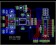
Updated Board Layout
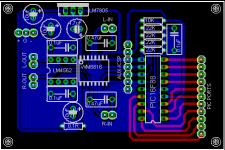
I have attached a picture of the updated board layout. Basically I removed the input caps on the WM8816, changed the SPI pinout from the PIC and added headers for the controls, ICSP/ICD, and the remaining pic ports. I also added a protection diode to keep the 13V programming voltage out of the WM8816 if you are using ICSP to reprogram the pic. I also altered the power supply routing a bit. With the new layout I can easily remove the microcontroller section of the board and use a single controller to operate multiple preamp boards in a multichannel setup.
I plan on etching this desing tonight, and will likely assemble it tomorrow...I think I have all the necessary parts...
G.
Attachments
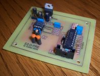
Hot Off The Soldering Iron
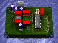
Well here is the actual board hot off the soldering iron. All that is left to do is hook up the input and output wiring and connect some sort of control buttons or pot...oh and finish the code for the PIC. 😀
Too bad I will be away this weekend, I'll have to wait until Monday to finish it up 🙁
G.
Well here is the actual board hot off the soldering iron. All that is left to do is hook up the input and output wiring and connect some sort of control buttons or pot...oh and finish the code for the PIC. 😀
Too bad I will be away this weekend, I'll have to wait until Monday to finish it up 🙁
G.
Attachments
Member
Joined 2002
jleaman said:Im interested to know how it sounds when all complete 😀
I hope it doesn't "sound" at all 😉
I'll be sure to let you know if it is any good.
G
Hi
I like your design/idea & thought I would have a go along similar lines.
In trying to design the board, I noticed that there may be a problem with your schematic (& hence the board itself) inthat according to the datasheet I have for LM4562, the V- supply is pin 4 and the V+ is pin 8.
Apologies if I am wrong on this as I'm a bit new around here......
I just wouldn't like you to waste a good ic 😱
Mike
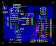
Yup...I goofed when I drew the schematic. I mirrored the opamp symbol to get the - input at the top...but neglected to realize that the PSU connections also flipped. It made some lovely smoke when I switched it on, even chewed up 2 transistors and 3 resistors in my PSU 😱 Quite a stupid mistake if I do say so myself...fortunately I was testing it with an OPA2134 😉 Now to figure out how to get the smoke back in!
Not to worry though I reworked the layout with a few other changes. I just haven't had time to put it together. I removed the input caps, and also changed the supply routing to correct the original issue and also seperated the PIC/volume IC supply from the opamp supply. I also went for a star ground instead of a groundplane. I am going to run this from a much more simple regulated supply than the one I was using, especially given the excellent PSRR of the LM4562. I just need to find some time to put it all together.
G.
Attachments
Right, you are. I'm guessing he hasn't powered it up yet.MikeBarton said:... the V- supply is pin 4 and the V+ is pin 8.
- Status
- Not open for further replies.
- Home
- Amplifiers
- Chip Amps
- WM8816-LM4562 Board Design