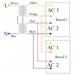
After soldering up the kit i bought from chipamp.com im pretty eager to test the power supply boards and see if I get the right output from em.
problem is i bought the dual mono kit and have two psu boards... and one transformer with 3 sets of 2 wires. blue and brown are input then i have the pairs of red and black then yellow and orange.
im not sure how to wire these to the ac1 ac2 inputs of BOTH boards. did i need two transformers or does the 3 sets of 2 wires mean i can use both boards with one transformer?
officially confused,
richard
Hi,
yes, wire up both PSU boards to BOTH sets of secondaries.
The power ground coming from each PSU board will be separate from each other.
I suggest you keep the dual mono set-up and retain the separate audio ground between the channels as well.
When you get around to making this dual mono set-up safe to use you will need to connect the two separate channel audio grounds to the Safety Earth.
I suggest you try using two independent disconnecting networks to make the safety connections. If this fails to give low noise, then direct connection between the audio grounds and Safety Earth may be better but this relies on very close/very short grounding connections between the channels and this can be difficult to achieve.
If all these options/solutions fail to meet your standards then twin transformers is your next route.
might sound stupid but my problem is that i dont know which colours are ground i can guess but... and i dont know what one to connect to either ac1 or ac2 on brians kit....
thanks for the help anyway it was useful
thanks for the help anyway it was useful
Hi,
Firstly, build up a mains light bulb tester.
Use it to power up every project for the first time to avoid expensive/dangerous failures due to mis-wiring. And keep it for powering every time you modify any project.
Identify which secondaries are connected together.
One pair go to AC1 and the other pair go to AC2.
so negative and positive of one secondary go to one ac. (ac1) then the other to ac2...
erm ive got two psu boards which is where i get confused....
thanks again
erm ive got two psu boards which is where i get confused....
thanks again
it sounds like you just need to solder a set of wires to AC1,AC2,ACG1,ACG2 on the transformer or get another transformer.
Hi,
don't call your AC wire connections positive and negative. That will confuse both you and us.
Flow and return, or Hot and cold, or Live and Neutral are acceptable alternatives that get adopted depending on context. I'm sure there will be other names that get used and are less confusing.
don't call your AC wire connections positive and negative. That will confuse both you and us.
Flow and return, or Hot and cold, or Live and Neutral are acceptable alternatives that get adopted depending on context. I'm sure there will be other names that get used and are less confusing.
info on how to wire one transformer to psu PCB is what he needed. even i see that from the first post. not tring to confuse anyone.... at the rate you were giving answers it would have prolly taken 2 more of your posts for him to finally get his answer.
fusion said:so negative and positive of one secondary go to one ac. (ac1) then the other to ac2...
erm ive got two psu boards which is where i get confused....
thanks again
In that case, its perfectly fine to use just one PSU board. Do, however, make the cables to amplifier 1 exactly the same length, and exactly the same length as to amplifier 2. 😉
It isn't necessary to braid, but do keep the hot lines within 1/4" or closer to the ground lines (close to each other).
I have absolutely no idea how to wire the common ground to the case if using a stereo pair and a torrid transformer. Can someone help out here?
fusion said:so negative and positive of one secondary go to one ac. (ac1) then the other to ac2...
erm ive got two psu boards which is where i get confused....
thanks again
I have attached a picture which should give you a clue how it could look..
There should be a picture on the side of the transformer which you should use to check the colours are the same..
The metal case (if you use one) should connect direct to the mains earth. Both of the ChG's (channel Grounds), should also connect to earth . If it hums then check other threads for info.
Please follow info about safety posted by AndrewT..
Attachments
audio1st said:If it hums then check other threads for info.
Nice chart!
Hey, there's less hum if you use same length leads for both power supplies. Also good is same length leads for both amplifiers.
Another fix for humming is to avoid metal to metal contact of potentiometer or signal terminals, with a case that is already grounded. This option that may stop a hum. I mean, use just one ground for the case--not several.
Oh, and do make the signal cables same lengths for both right and left amplifiers. That way you can plug in a common ground source like a computer, ipod, most CD players, etc. . .
omg lmfaoooo i think i just fried my psu components. hooked up the transformer to onee of my psu boards (brians snubber) as shown attached...
the board started humming and the blue light came on then faded. now the capacitors are wayyy too hot to touch... i got another psu board but i dont wanna do this again... any advice?


the board started humming and the blue light came on then faded. now the capacitors are wayyy too hot to touch... i got another psu board but i dont wanna do this again... any advice?
An externally hosted image should be here but it was not working when we last tested it.


without using a mains light bulb tester.fusion said:omg lmfaoooo i think i just fried my psu components. hooked up the transformer
a very good point. took the risk after realising im only gonna use one board. im probably gonna get flamed off the forum now, but if anyone wants to stop a massive hifi fan and pretty useless DIYer from binning a perfectly good kit... id appreciate it...
If it was really hot then part or all of it was backwards. One or the other.
So now just check the caps and see if there's any deformities.
Check the diodes for conductivity (they're just like light bulbs inside).
And just replace any bits that got fried.
Its probably none, or maybe a diode expired.
Howabout putting a nice 100w light bulb in-series with the AC input (bulb in-series with mains power cord) before testing again?
It might help to view your torroid as two transformers. Each powers half of the power supply.
😉 P.S. I knew that I would do that very same thing so that's why I use a CT, made the mod, plugged it in and never gave it a second thought.
That's because I took one look at a torroid, thought: "I'm going to pay extra to get really confused?" No way. I'm already confused enough. 😉
i appreciate the help. caps were hot for ages but no deformities... multimeter thinks diodes are fine.... ok my electronics knowledge isnt non existent but i just ... tend to do silly things.
im in the process of building a bulb holder ... should be interesting.
ill post how i get on. thanks
im in the process of building a bulb holder ... should be interesting.
ill post how i get on. thanks
anddd it would help if someone could clarify the ac1 ac2 thing...
out of the transformer i have 2 of the 0v wires and 2 of the voltage carrying wires...
do i.. connect both 0v to ac1 and both voltage wires to ac2... coz thats NOT what i did ...
:S
out of the transformer i have 2 of the 0v wires and 2 of the voltage carrying wires...
do i.. connect both 0v to ac1 and both voltage wires to ac2... coz thats NOT what i did ...
:S
fusion said:
one transformer with 3 sets of 2 wires. blue and brown are input then i have the pairs of red and black then yellow and orange.
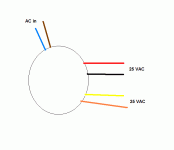
My guess is red/black is one secondary and yellow/orange is the other.
Connect the transformer to the mains (through the light bulb limiter, don't ignore good advise) without connecting the PS board.
Use your meter to read the AC volts across the red/black pair. Assuming this is a dual secondary transformer, the same voltage should show at the yellow/orange leads.
EDIT: An illustration:
Attachments
- Status
- Not open for further replies.
- Home
- Amplifiers
- Chip Amps
- wiring up a transformer (brian gts kit)

