Might write pages about it, but the short answer is: don´t.So I considered adding resistance to bring the speaker's to about 6 Ohms each.
I will need to experiment driving the speakers with and without added resistance to determine what is best.
Just consider them 4 ohm, whatever the speaker manufacturer states, and drive them with competently designed amplifiers whose designers also consider the fact that standard speakers normally have somewhat lower impedance at some frequencies than official rating.
So don´t compensate what´s not required.
Hi there Marcel, that was my concern from the beginning. I had beenl led to believe that the units were in fact 8 Ohms so it came as a shock to find that they measure less than half that. In fact the whole system concept was based on their being 8 Ohms.
One option would be to regulate the lower voltage rails back to about half the original design value - assuming this will not interfere with proper amplifier operation, such slew limiting or switching between supply rails. Another is to buy a new transformer with reduced secondary voltages to suit the lower impedance load but that is not a cheap alternative, given that I have already bought a transformer for this project.
Perhaps the best option is simply larger heatsinks - that might be less expensive than a new transformer - but will cost more than regulating the inner supply rails.
At issue here is that the amplifier intended for use is a class G because the system is to be three way active.
The amplifier was designed for 8 Ohms load and the switching between lower and higher voltage rails was determined to be at a predefined (30W) power. This can be modified of course by exchanging the relevant zener diode, as well as reducing the inner supply rail voltages but I am reluctant to mess with the established design.
The amplifier was designed for 8 Ohms load and the switching between lower and higher voltage rails was determined to be at a predefined (30W) power. This can be modified of course by exchanging the relevant zener diode, as well as reducing the inner supply rail voltages but I am reluctant to mess with the established design.
Many thanks to all who responded to this thread - seems that I've worried unnecessarily. testing has shown only a minor increased heatsink temperature after three hours of normal use - and all else is working exactly as it should - except that the rail switching occurs at around 50Watts - not 27W as would be the case into 8R speakers, but I can live with that.
Moreover I can thoroughly recommend Doug Self''s class G power amplifier - it worked perfectly from the instant of 1st switch-on and seems completely reliable.
Moreover I can thoroughly recommend Doug Self''s class G power amplifier - it worked perfectly from the instant of 1st switch-on and seems completely reliable.
Pass DIY Addict
Joined 2000
Paid Member
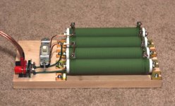
I'm a little late to this discussion, but a little while ago I measured some large wire wound resistors. Using my quick and dirty LCR measurements, wire wound resistors do have some inductance, but it is so very small for the resistors I measured that the inductance gets swamped by nearly everything else.
I have attached an image of my resistors, I use these as a dummy load for measuring amplifier output power.
Here is the link to the measurements I made of them.
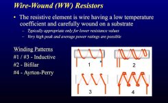
I'm not sure where I originally found these, but here is some additional information on various ways that wire wound resistors are constructed.
I have attached an image of my resistors, I use these as a dummy load for measuring amplifier output power.
Here is the link to the measurements I made of them.
I'm not sure where I originally found these, but here is some additional information on various ways that wire wound resistors are constructed.
Attachments

Last edited:
...not understanding the mechanism by which you converted my measurement to an additional resistance rating at 20kHz....
Inductance * 2 * 3.14 * Frequency = impedance.
4.2uH * 2 * 3.14 * 1kHz = 0.026 Ohms
4.2uH * 2 * 3.14 * 20kHz = 0.53 Ohms
Relative to 8 Ohms, this additional impedance run from "none" to "small".
If you run to 303KHz the inductive impedance gets as big as the resistance and all measurements based on "8 Ohms" are dubious. Since modern transistor amps will "do something" at 300KHz we need to know.
But for padding wound-coil loudspeakers it seems clear that wirewound resistor inductance is quite negligible.
Pass DIY Addict
Joined 2000
Paid Member
Thanks for the details, PRR! I've been at this for a while now and I still feel like there is a ton that I don't know. I appreciate your help in filling some of the gaps!
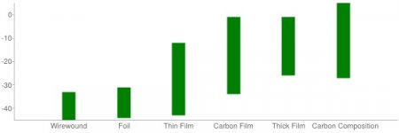
Resistor Noise >> Resistor Guide
Very low noise resistors 🙂
Wirewounds are the best for use in the input stages, preamplifiers, phono, crossovers etc.
My personal experience: metal films were replaced by wirewounds in valve line stage and sound is incredible now.
The cost is high for MRA Mills but industrial quality and Ohmite are affordable.
Is worth to try, but not many audio Diyers do in reality. Have a nice day
Attachments
- Status
- Not open for further replies.
- Home
- Design & Build
- Parts
- Wirewound Resistors: Impedance vs Frequency