Hi all,
Wirewound resistors are coils - so does their resistance change within the audible range of frequencies ?
I need to 'pad' the speaker coils (2R8 at DC) with series connected resistors to raise the overall impedance to at least 6 Ohms @ 50Watts.
Many thanks, any advice would be greatly appreciated.
Wirewound resistors are coils - so does their resistance change within the audible range of frequencies ?
I need to 'pad' the speaker coils (2R8 at DC) with series connected resistors to raise the overall impedance to at least 6 Ohms @ 50Watts.
Many thanks, any advice would be greatly appreciated.
The inductance of wirwound resistors isn't crtical in the audio range up to reasonable high values yet you could buy non iductive wirewound resistors like Welwyn ...:
Last edited:
Hi dreamth,
Thanks for your response, so can I assume that their resistance remains constant - or nearly so - at all audio frequencies ............... and what of the loudspeaker voice coil, surely its impedance must be frequency dependant ............... ?
Thanks for your response, so can I assume that their resistance remains constant - or nearly so - at all audio frequencies ............... and what of the loudspeaker voice coil, surely its impedance must be frequency dependant ............... ?
I saw hundreds of speakers filters with regular cemented wirewound resistors...I used welwyn non-inductive resistors in the anode of high transconductace valves as the current x voltage product was high and the value was 4.7k...33k...I could measure clear 25khz square waves on them...but i can hardly believe that you need something like this with a 4.7 ohms 5...50w resistor...It won't hurt using non-inductive though 😉
Loudspeaker datasheets usually have impedance versus frequency graphs in them. The low-frequency resonant peaks are very dependent on the loudspeaker enclosure if the back side of the loudspeaker is open. The high-frequency part of the graph does not.depend significantly on the enclosure.
Look at a coil. Look at a resistor. The coil has many more turns more bunched-up.
The inductance can matter on the 0.1 Ohm wirewounds in amplifier bias networks, but even then it rarely gives trouble.
At few-Ohms you are probably fine all across the audio range. It takes more "coil" than a resistor has to reach a few ohms of inductance.
Anyway your LOAD is a wire-wound resistor. The Voice Coil. Which moreover has an iron slug in its heart. VC inductance likely exceeds anything you will find in a wire-wound.
I have not seen data for a normal wirewound, but Ohmite state a remarkable <1nH@1MHz for their non-inductive WH type. This hints that the normal type in the values used in speakers are going to be well behaved to 20kHz
Hi all,
Wirewound resistors are coils - so does their resistance change within the audible range of frequencies ?
I need to 'pad' the speaker coils (2R8 at DC) with series connected resistors to raise the overall impedance to at least 6 Ohms @ 50Watts.
Many thanks, any advice would be greatly appreciated.
The formula for a solenoid coil is easy to find, if you know the size and turns you can calculate the inductance of a wire-wound, and calculate the cut-off frequency as R/L.
Any resistor has series inductance whether a coil or not, so this applies universally, but it would be hard to construct a resistor with a cutoff near audio frequencies unless it was wound onto iron or steel.
As an example, the 15ohm WW resistor in this test had ~0.7µH:
Building my own noninductive 8R 150W load using wire wound resistors
Completely negligible compared to the voice coil
Building my own noninductive 8R 150W load using wire wound resistors
Completely negligible compared to the voice coil
Just a couple generic real world speaker inductance values.
* Dayton Audio 10" woofer: Le=2.63 mH
* Dayton Audio 4" full range speaker: Le=0.5mH
* Peerless 1" silk dome tweeter: Le=0.04 mH (50X higher than elvee´s resistor)
so we see that compared even to very light , tiny tweeter voice coil, resistor inductance is barely 2% of its value ... completely negligible.
I bet the speaker cable joining speaker to amp has comparable inductance.
> 15ohm WW resistor in this test had ~0.7µH
For non-math folks: 0.7uH at 20KHz is 0.1 Ohms(*) so not even 1% "error" on 15 Ohms.
(*) 0.08796459.. Ohms if you must be fussy.
For non-math folks: 0.7uH at 20KHz is 0.1 Ohms(*) so not even 1% "error" on 15 Ohms.
(*) 0.08796459.. Ohms if you must be fussy.
Many thanks to all who have responded, I think that answers my question - one point though - does the impedance of a loudspeaker vary from its dc ohmic level when driven within its useful frequency range ?
Yes, very much so: think of the resonance frequency.
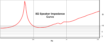
It is an extreme, of course, but if you look at the impedance curve provided in all good datasheets, you will see that it is far from flat, even if you exclude resonance
It is an extreme, of course, but if you look at the impedance curve provided in all good datasheets, you will see that it is far from flat, even if you exclude resonance
PS: Please ignore my last post : I hadn't realised the obvious, that speaker impedances do vary, sometimes largely.
I looked at a number of performance graphs of fairly typical/common makes, and it became clear immediately.
I am in the process of constructing an active system, using speakers which although labelled as 4 Ohms, actually measure only about 2,8/2,9 Ohms DC. Such a low impedance would be unacceptable - hence my original post querying wire-wounds.
Once again, many thanks for all your responses.
In fact, looking at such graphs as you suggest, I see that impedance starts at a given level, then rises (steeply in some cases) at the speaker's resonant frequency, then falls to a level close to it's DC value before rising gradually with frequency.
The nominal impedance of your speaker is 4 ohm. You may regard this as a sort of average value for the impedance of the speaker (which, as you say, varies with frequency).PS: I am in the process of constructing an active system, using speakers which although labelled as 4 Ohms, actually measure only about 2,8/2,9 Ohms DC. Such a low impedance would be unacceptable - hence my original post querying wire-wounds.
If your amplifier is 4 ohm capable then there is no need to 'top up' the impedance with wire wound resistors.
Attachments
PS: Please ignore my last post : I hadn't realised the obvious, that speaker impedances do vary, sometimes largely.
I looked at a number of performance graphs of fairly typical/common makes, and it became clear immediately.
I am in the process of constructing an active system, using speakers which although labelled as 4 Ohms, actually measure only about 2,8/2,9 Ohms DC. Such a low impedance would be unacceptable - hence my original post querying wire-wounds.
Once again, many thanks for all your responses.
DC resistance of a driver is not directly relevant, unless you are planning to drive them with a DC source, and audio amps are not generally designed to do that, and responsible designers build audio devices to prevent that.
Also, nearly all "4 ohm" drivers will measure around 3 ohms DC...that's totally normal.
And since you are using active crossovers, there's no need to be concerned about the sliding impedance of the drivers at all, assuming the amps are rated to drive their nominal impedance.
Mike
The intended amplifiers are Doug Self's class G - no doubt they will drive 4 Ohms without problems. I designed the PCB's to provide for doubling the output transistors to halve the current per device, the power supply will easily provide the additional current but there may be an issue with heatsinking. The 'sinks are quite efficient at 0,4 °C/W, but are only 200 x 100 mm, which is adequate for each single channel amp into 8 Ohms, but maybe not so into 4 Ohms. So I considered adding resistance to bring the speaker's to about 6 Ohms each.
I will need to experiment driving the speakers with and without added resistance to determine what is best.
I will need to experiment driving the speakers with and without added resistance to determine what is best.
That boils down to using about half the amplifier's power for heating up resistors and getting a very frequency-dependent voltage division between resistor and loudspeaker. Can't you add some kind of thermal protection instead, or reduce the supply voltage a bit if the amplifier can handle that?
Hi Gerry!
Adding resistors in series with mid/bass speakers, as you appear to suggest, would work, but is not a good idea.
As Marcel has just said, a lot of amplifier power will be wasted as heat in the series resistors and you would need to use very high power resistors.
Adding resistors in series with mid/bass speakers, as you appear to suggest, would work, but is not a good idea.
As Marcel has just said, a lot of amplifier power will be wasted as heat in the series resistors and you would need to use very high power resistors.
- Status
- Not open for further replies.
- Home
- Design & Build
- Parts
- Wirewound Resistors: Impedance vs Frequency