You may need to add a dominant pole to the design. The first 100k resistor from plate to HT needs a series resistor and cap. Try 10k and 330pF in series across the 100k plate resistor of the first stage. The GNFB should be from the 8R tap? You will have to experiment with the cap value. Watch your tweeters.
Last edited:
I have found the problem and I have to say I'm quite disappointed. Maybe a nube move on my part trusting and placing too much confidence in expensive audio capacitors.
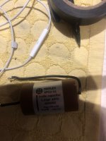
The only upgrade I've done was to replace the 4 x 0.22uF capacitors with brand new Miflex KPCU-01. This upgrade and exact product was used my other members on other forums as well. Although it improved the sound, one of the 4 caps obviously has some fault as it causes these oscillations when increasing the volume in triode mode.
Willsenton support send me some troubleshooting steps thinking it's one of the tubes that's causing it. I will post their instructions in my next post so others could follow it as well in case they develop issues. Basically they said that if the issue exists in one channel it could also manifest itself in the other channel although the other channel doesn't have an issue per se. So I narrowed it down the issue being on the left channel only and no faulty tube. My next thing was to undo the only upgrade I've done which is these caps, narrowing down to one cap. This cap is not cheap for me, CAD $40 plus "canadian" taxes. I'll try to contact Miflex and see if they can do anything about it.
All this was caused by a relatively expensive, brand new, exotic, Pap+PP+Oil cap.
Thanks again for all your help as I've learned a lot from all your input. I hope it will also help others on this forum in case they develop issues in the future with their Miflex upgrades.
Attachments

Troubleshooting instructions I've received from Willsenton support........
At first, we need to remove all the RCA cables on R8, no any RCA cables on R8, if we can find out no any noise, humming or buzz when no RCA cable on the R8, that means the R8 is in good.
The noise, humming or buzz come from the RCA cable (sound source). We can work together to try to resolve the problem about RCA cables (sound source).
After remove the RCA cables, we can do the test as below, please remember all the testing below need to work without any RCA cable on the R8.
Please send a picture to show the tubes on the R8 to me, the 6SL7 and 6SN7 looks a little similar, but they are not the same. We remove all the tube for the R8 before sending because it is safer, but, we found some buyers plug the 6SL7 and 6SN7 wrong.
According to your emails, seems the all tubes on the R8 can not find out which tube is bad.
So, We can try the one channel only. Sometime, one tube is bad can make 2 channel have noise too.
Test A,
Stay the V1, V2 , V5, V6, V7 at tube amp.
Adjust Bias for the KT88 V1, V2, test, and tell me if the noise is there.
Set the Meter pin at the middle of the big point.
How to Bias?
Adjust the volume from the the lowest to highest, if the noise changed when the volume changed.
After test this,
Test B,
So, We can try the right channel only.
Stay the V3, V4 , V5, V8, V9 at tube amp.
Adjust Bias for the KT88 V3, V4, test, and tell me if the noise is there.
Set the Meter pin at the middle of the big point.
How to Bias?
Adjust the volume from the the lowest to highest, if the noise changed when the volume changed.
After test this,
Test C,
If both of channel have noise when just test one channel again.
We need to exclude if the V5 tube is bad.
Remove the V5 tube, Don’t use the V5 tube at Test C.
Change the V9 tube to V5 tube socket, test. Just LEFT channel test.
Do Test A, with new tube 6SN7.
Tell me what happened?
After test this,
Test D,
If both of channel have noise when just test one channel again.
We need to exclude if the V5 tube is bad.
Don’t use the V5 tube at Test D.
Change the V6 tube to V5 tube socket, test. Just one channel test.
Do Test B with new tube 6SN7.
Tell me what happened?
Please remember that need to Adjust Bias after you change to another tubes KT88, even different tube socket, need to adjust Bias.
Sometimes, if the Bias is not at the middle point, it may make some noise too.
If we test all of this, we will know if any tube is bad.
Attachments

I feel stupid now bashing Miflex.
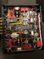
I tried to place the "faulty" cap in a totally different location. I tried this already but left the cap in the same vicinity as the big power cap. It's weird that the other side doesn't have the same issue although it's also close to a large power cap. Is this an indication that the power cap has some major leakage? Or is it the output transformer behing the power cap. The side with the issue is a mirror setup as the other side that has no issue.
Live and learn. Happy there was nothing wrong with anything and it was just a positioning problem aka user problem.
Thanks again.
Attachments

One more quick question. During the tube testing and swapping, found out that one of the power tubes requires about 20mA less bias than the other 3 power tubes (KT88). Basically I can swap around the 3 tubes and their biasing was a very close match to each other. The one tube though required a significant less bias compared to the other 3.
Does that mean they're not a matched quad and should I be concerned? I can bias all 4 to match though.
Does that mean they're not a matched quad and should I be concerned? I can bias all 4 to match though.
It's actually a token gesture amount of NFB < 6dB. This is shown up in your triode mode where the gain drops significantly. So I cannot see that being the source of your issue.
I've done a simulation both in triode and ultra mode. Again no sign of an issue. This is with an accurate Hammond OPT rather than the one you have.

I've done a simulation both in triode and ultra mode. Again no sign of an issue. This is with an accurate Hammond OPT rather than the one you have.
Last edited:
The only thing I can see is that the .22uF should be kept away from the 1'st stage. It's just possible they are so big that the signal is coupling back into the input. I would have been happy with mk2/mk4's myself but hey! Unlikely but just a suggestion. The +225V decoupling is OK you may need a film cap across the electrolytic again unlikely. Your KT88 may have a fault but again why would it work in UL.
The problem was that one of the caps was close to the AC power wires and somehow it was interfering with its functionality at a certain stage. I moved the cap far from the AC wires and the moise went away and i’m happy again.
Thanks
Thanks
Maybe you had a small arc on the peak of the signal. In triode mode the drive level is higher. Glad its sorted.
It's interesting that the distortion and output damping factor can be improved by some increase in the GNFB.
With one component change and the addition of two components to create a dominant pole the distortion drops by 10dB. The input sensitivity is now 800mV but that's fine with modern inputs.

With one component change and the addition of two components to create a dominant pole the distortion drops by 10dB. The input sensitivity is now 800mV but that's fine with modern inputs.
I have hardwired the relay and it has the same problem.
Any other advice on what else it could be? The fact that it happens on both channels equally leads me to believe that the issue has been there since new.
What did you do exactly?? thinking myself i wanna remove the UL mode (and the relays. Did you use like 100-220ohm resistor between pin 3 and 4? Didi you use the blue wires on OPT only?
Skunkie design measured and got best result with 24K paralell with 110-330pf cap (maybe 220 is the spot) Response looked much better
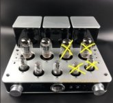
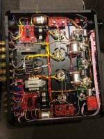
One thing, the grounding inside this amp is an absolute mess, especially how they ground the output tube cathodes through one leg of the heater wiring and is no where near "best practices". Neither is the header wire layout in general. I also noted triode mode sounds bad on this amp (honestly I didn't dig into that as I prefer the sound of UL amps in general) and honestly any of these amps I have played with that had a "triode/UL switch" sound bad in triode mode. If you really want triode mode, hardwire it and tune the GNFB for it. You might not even need GNFB with it triode wired.
I updated the grounding and bias mod according to Skunkies suggestion and it just sounds much better. Bass is tighter, more open mid, more detail but same time smoother. Also noticed when measuring cathodes if my needle is in middle with my blue JJ kt88 im biased at about 0.44V… but when needle is on last mark its about 0.52-0.53 and that also improves the sound.
Would like to do the triode only mode but little unsure how to do without destroying the amp (even though i have done it before with a Yaqin Mc100b many yrs ago.
Also gain is very high with this amp. I can go past 8.00 or 9.00 with my 93+ db speakers. Dac is Denafrips Pontus 2.
Would like to do the triode only mode but little unsure how to do without destroying the amp (even though i have done it before with a Yaqin Mc100b many yrs ago.
Also gain is very high with this amp. I can go past 8.00 or 9.00 with my 93+ db speakers. Dac is Denafrips Pontus 2.
I think the front end of this amp has WAY too much gain. It doesn't need a 6SL7 and I think a redesign using a 6SN7 or some other lower gain tube would help it a lot.
Should we then start a new thread about this conversion to another tube? 😉
First thing I'd try would be to totally eliminate the 6SL7 from the circuit. Just send the output of the volume pot directly to the 6SN7 driver / phase inverter stage. I'd try this temporarily to see if you have enough gain. If you do, then you can go back and disconnect the PS node that supplies the 6SL7s. All the unused tubes (two 6SL7s and one 6SN7) can be disconnected and left in place so you don't have empty sockets.
You'd also have to figure out a new NFB scheme. I assume you'd take the FB to the cathodes of the 6SN7 driver / phase inverters instead of the 6SL7 input. Might need a different value R and/or a cap added.
If this goes too far and you now find that you don't have enough gain, I'd replace the two 6SL7s with a pair of 6J5GTs. The 6J5 is a single triode equivalent to half a 6SN7. Just cap couple it to the 6SN7 driver / phase inverters.
You could also just add a voltage divider in there somewhere, I suppose. That would probably be the simplest thing to do.
Re: Conversion to triode . . . I thought these can be switched to triode. If you want to do it permanently just hard wire it and eliminate the switch. If triode mode doesn't sound good it's likely because the amp uses the same amount of NFB no matter which mode is used. Triode is most often run without NFB or very little.
Last edited:
I ended up getting a nice looking square wave with those OT using GNFB of 24K and a 330pf cap across it. When I was doing this mod I was running out of time, and I only had a pair of 110pf and a pair of 330pf to play with. The amp sounded a bit flat with the 330pf so I put the 110pf back in before I returned it to the owner. The square wave wasn't totally good with the 110pf but was better and lower values did nothing visible on my scope. I did play with a 5.6K GNFB Mod as someone was telling people to do this simply by ear, and the square wave was doing some really crazy stuff, like on the verge of being unstable. while 10k might look good on a sim, I'm not sure these output transformers can handle that. I wanna play with it again later as I think 24K/220pf might be a better option.
- Home
- Amplifiers
- Tubes / Valves
- Willsenton R8 heavy distortion in triode mode