Go to YouTube and search "boom bap" or "trap" type beats.
Thanks! Not a HH fan, but am curious about anything music related. Hope this basic HP workbook has a good enough sound-card + cheap headphones to be of any use.
Now play that type of kick drum or whatever that is in any music. its upper bass nores for the very top of subwoofer upper XO points unfortunately. Except? Heres a thing(suggestion) . Listen to anything like that.
— sealed box 1 ft3 for a similar but slightly larger Vas.
—- offset driver Pipe with zero ‘path’ separation to sum. 100cm between each fold and the ends of the pipe(s). 100cm ,200,300.... 300cm as the qw of 1200cm.
—-compound qw pipe. Zero path, infact, less that that word hints at in HR. 200cm and 100cm with 100 cm at the end with another 100cm affectively to the exit phase sum.
—- offset driver qw pipe Mass loaded in series reduction. 150cm between folds, twice the CSA ised in the first fold as the last, and use the middle fold to csa to ensure the affect. 150 cm at (2x ) cm2 then fold to 150 cm and fold to 150 cm at (x) cm2, exit at drivers other output.(no ‘path’).
I enforce the ‘no path’ by making a specific design which also caters to the actual lengths found in HR at the TH/OD interface of 90 degrees in phase as Nd/OD (a plain pipe if used) for its fundamental at exit. Vs polar opposites(meaning the direct radiators phase at 90 instead of 180 if it was a helmholtz Fb.
Now using TH 0.01cm you arrive at a slightly skewed to the offset pipe side if splitting hairs or folds in this case(its not .3334. Its .349 or so as GM has always stated and long before we had a way of actually knowing he pretty much did. But there it is. and it gets washed out of things by not using the right pipe size or length for a driver(TS parameters). Vas and qes-qms (on the Fs) for a length past or less than Fs (not QW, full wave).
But theres the higher order element here, yet the layout can be very similar. Or pieces of it and phase. And if you reference both outputs and the full wave length. Using that 90 degree reference as 1/3 of a full waves frequency you get to specify or classify a end result as a ‘difference’ using sealed as the control/reference to zero-plain, etc. which means half in any direction is not as good to a single polar element by however you want to describe that(good/bad/ugly, its still a mathematical thing if you reference one as the sum of some point.
That is how we can share objective or subjective or adjective loaded comments on thoughts with a ear to phase look at true qw pipe action not guesses?
How far from 360 are you at 720 and 7200degrees. Cause in there is the harmonic truth to everything. Not just random guesses with a slider tool to a lucky result that kinda works regardless, but is not based on anything or ‘learning anything(?)??
I so want to add a polar graph of degrees. And the harmonic in the next and then the next and spin that pi, around and around to cover 10 turns. the math for plotting that sinewave from x/Y to a polar coordinate of rotation would be
R=2+2(cos theta)
Theta =pi/2
But the (2+2) part is (2+1) think(im
Sorry to say it's been 20 years since i used calculus or trig or pythagofancymath forms of it to describe radioactive isotope decay thru reactor plant shielding and distances of air to humans or a thermal neutron to a uranium235/238 but i swear that all comes full circle like deja Vu the day you step into either one on the deep end?
Considering the high Le of that driver, the semi-inductance parameters should definitely be included in the model. Those will change the response at the higher end of the passband by a bit.
Not only that, if using red LE, the tendency to tune lower than one might otherwise for a Qes/Qts is now subject to doubling or more. If Le/Re is <> 1.0 <>. The impedance plot and driver data will show this. However, the red LE has proven itself to be a very legitamate tool when green or black werent. Thats up to the layout and everything involved. and simply put, its just another way, like a person uses an easy acoustic shape but then adds a Re to a Qms change unpurspose. i aint gonna win that or sell it. Just suggesting it in leu of one way or another in regards to application in HR sims of higher order or higher loading or offset pressure phases as a differntial on a cone.
As per Brian's advice, i asked manufacturer to supply detailed t/s parameters of this driver. And - yes, Le is included in the model, as can be seen in the screenshot.
Le is the value of the driver's inductance at one particular frequency, usually 1kHz for subwoofers.
Unfortunately the driver's inductance is not a static value - it varies with frequency. And with some subwoofer drivers, this variance is significant enough to appreciably alter the frequency response in comparison to what's predicted by speaker models that don't take this into consideration. The extra "semi-inductance" parameters can be used to take this variance into consideration, to produce a more accurate simulation.
Very few manufacturers, if any, quote the semi-inductance parameters. However they can easily be derived from the driver's impedance curve.
Thanks! Not a HH fan, but am curious about anything music related. Hope this basic HP workbook has a good enough sound-card + cheap headphones to be of any use.
You're welcome guy! Today's RAP music is TERRIBLE. The beats are nice but the lyrics are HORRIBLE. When I am in my car, I listen to trap intrumentals. When I'm at work (home = 5.1 and office = headphones), I listen to Boom Bap Hip Hop.
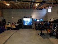
The table on the right was built in 1998 with 2 12's in a BP4.
Attachments
You're welcome guy! Today's RAP music is TERRIBLE. The beats are nice but the lyrics are HORRIBLE. When I am in my car, I listen to trap intrumentals. When I'm at work (home = 5.1 and office = headphones), I listen to Boom Bap Hip Hop.
The table on the right was built in 1998 with 2 12's in a BP4.
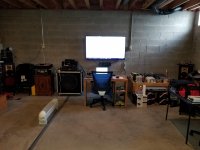
Oh man, cinder block walls, neighbors harder to bother... lucky! I load stuff in an RV and drive...
I love it! I want to upgrade to an all PA speaker 7.1 setup like the mancave but the wife doesn't let me turn up the current 5.1 setup when she is working from home too.
The basement Onkyo HT-R570 is a 7.1 receiver that came in the 2009 HT-S5200 home theater in a box. The 7 surround speakers are in my son's apartment connected to my ex-Pioneer VSX-1022-K 7.1 receiver. The 10" subwoofer is in our dining room connected to a Yamaha HTR-5730 5.1 receiver. I listen to the dining room system while I'm in the kitchen.
I have 8 separate audio systems in my house if you include the intercom system that has FM/AM radio. I might listen to the intercom when we're cleaning house with all the windows open.
Most of my audio equipment I got for free. The 18" bass bin in the basement was free from our church. I also got a center channel from them that's in our son's bedroom in a 5.1 system. However, I did rebuild their audio booth for free when they moved locations. Both speakers were sitting in their back room doing nothing.
I got the Yamaha AVR for free after installing TWO AVR's in a woman's house that worked with my father at Ohio State University. She upgraded to HDMI. I also got her Pioneer stereo receiver just sitting in the basement as a backup.
The 12" subwoofer in our son's bedroom was a freebie when my buddy closed his car audio shop. He also gave me 4 Yamaha 8" 2 way surround speakers in our master bedroom, the two 10" Fisher 3 way towers in our son's bedroom, and a Sony center channel in the office next to our son's bedroom.
The Sony 2.1 soundbar system in our master bedroom was a Christmas present from my father along with the Sony STR-DH710 7.1 receiver in our son's bedroom. I rewired the 3 speakers in the soundbar to center channel duty and connected the 4 Yamaha speakers to make a 3.1 system.
My father also gave me the 2 surround speakers in the office, the two 12" Motown 3 way speakers in our son's bedroom, the 2 KLH speakers in basement being used as a center channel, and the 2 surround speakers in the dining room.
I bought a 2nd Sony STR-DH710 off of craigslist for the office. The Sony 6.5" subwoofer in the office was a freebie from the wife's best friend. Her home theater system is mostly my ex-AV equipment that I gave to her.
The garage has Sony towers with a built in Dolby Surround amplifier and 5.25" BP6 subwoofers. I remember getting those speaker off of craigslist in the early 2000's for $50 to go with a 1997 Sony 53" rear projection TV. I could never get the TV to control the amplifier or vice versa. I think I needed 1 model up on the TV to control those speakers. I got rid of the TV last April when I upgraded to the 55" TCL in the basement.
Attachments
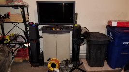
I forgot, the spare bedroom has a Midland 2.1 computer speaker system connected to a 24" Curtis 1080P tv. Guest can "bump" off an Amazon Fire Stick.
Le is the value of the driver's inductance at one particular frequency, usually 1kHz for subwoofers.
Unfortunately the driver's inductance is not a static value - it varies with frequency. And with some subwoofer drivers, this variance is significant enough to appreciably alter the frequency response in comparison to what's predicted by speaker models that don't take this into consideration. The extra "semi-inductance" parameters can be used to take this variance into consideration, to produce a more accurate simulation.
Very few manufacturers, if any, quote the semi-inductance parameters. However they can easily be derived from the driver's impedance curve.
That is interesting. BTW, the first Google result for term "semi-inductance parameters" is your post at parts-express' forum.
I will definitely try to derive those from that speaker a bit later. In an earlier post you said it affects the upper end of the passband. Is it still a concern if i intend to cut it at 40-45Hz at the upper end?
BTW, when crossing a TH, is LR24 a good type of filter? Coming from a car-audio world, i crossed everything with this type of filter.
If you're planning to x-over at 45~50 Hz, the impact of semi-inductance is going to be a lot less of a concern. Still, it would be helpful to include that impact in the model to see how much of a concern (or lack thereof) it is.
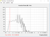
I think i found a sweet spot for this driver. Here is how the expected result looks compared to the previous sim (which basically was just a scaled version of the leaked SPUD design):

I've lost a few Hz of LF extension, but gained flatness and SPL. Oh and the spike at around 70Hz is a lot weaker.
Now, if only i could fold those horns as easily...
I've lost a few Hz of LF extension, but gained flatness and SPL. Oh and the spike at around 70Hz is a lot weaker.
Now, if only i could fold those horns as easily...
Attachments
The LR24 is down -6dB at the filter point. For the LP filter that may be what is desired, but for the HP (low cut) filter a BW24 (down -3dB at the filter point) will not cut as much at the low corner, better for getting the last few Hz of extension out of the sub without running into excursion limits.BTW, when crossing a TH, is LR24 a good type of filter?
Now, if only i could fold those horns as easily...
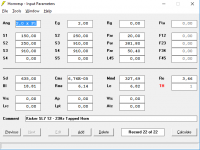
Show the HR input screen.
Now using TH 0.01cm you arrive at a slightly skewed to the offset pipe side if splitting hairs or folds in this case(its not .3334. Its .349 or so as GM has always stated and long before we had a way of actually knowing he pretty much did.
Hmm, not true as stated, so sorry if I accidentally indicated such. The 0.349 is what MJK derived from his 2D wave equation
Historically I've used a 3D equation for driver, vent, bend locations given me by my TL mentor that to the best of my knowledge is older than any acoustics math and does show a slight improvement in MJK's program, so is different for every HxWxD; which in at least two cases of large MLTL builds there was an audible difference [needed less internal damping] that resulted in one case of the owner removing ALL internal damping in his ~27 ft^3 pair.
Since he was a Symphony conductor, have to assume he wanted a 'sing along' speaker 😉.
Attachments
Attachments

- Home
- Loudspeakers
- Subwoofers
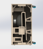
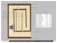
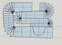
- Will this driver in the Tapped Horn configuration?