I found the SG505 schematic on Diyaudio.com and I'm thinking to build this.
Does anybody have a PCB for this?
Thanks for the help.
Best Regards,
Felipe
Does anybody have a PCB for this?
Thanks for the help.
Best Regards,
Felipe
The PCB which Cordell used for his Audio article can be found on page 11 of this PDF:
http://www.cordellaudio.com/instrumentation/thd_analyzer.pdf
You can save yourself a lot of headache by purchasing a used Wavetek, Krohn-Hite Oscillator, using the chassis, power supply and putting in new switch assemblies. The power supply should be well insulated from the rest of the oscillator -- you can even use some PCB material or a cut up beverage can to prevent emi and rfi from migrating onto the oscillator PCB.
Dear jackinnj,
I live in Brazil, here haven't that Oscillators... The unique option which we can have here is some China Function Generators, and the Goods Functions Generators from HP and Tektronix is really expensive.
That PCB at the page 11 is the PCB of SG505? In the page 12 there is a schematic different of SG505.
Are you certain?
Best Regards,
Felipe Navarro
The SG505 and the Cordell Oscillator use the same topology -- they are both state variable oscillators -- Bruce Hofer -- the inventor of the SG505 went on to co-found Audio Precision. Cordell credits Hofer at the end of the article on page 8 of the PDF. The paper is on the AES website "A Comparison of Low Frequency RC Oscillator Topologies" -- written when Hofer was at TEK.
The Cordell oscillator provides only a few number of frequencies, while the SG505 is continuously variable, but in reality, you don't need to check every little nook and cranny.
The Cordell oscillator provides only a few number of frequencies, while the SG505 is continuously variable, but in reality, you don't need to check every little nook and cranny.
If you really want low-tech solution for a low THD oscilator, then the lamp-stabilized wien-bridge is very good...especially if you use a low-wattage, high voltage lamp bulb such as a 240volt/3Watt .. these have very slow thermal reactance and will easely give you low THD...
Second hand is also very nice: I bought a Krohn-hite 4400 for ? 150$ off ebay.. wich give me <100dB THD...
Second hand is also very nice: I bought a Krohn-hite 4400 for ? 150$ off ebay.. wich give me <100dB THD...
tschrama said:
Second hand is also very nice: I bought a Krohn-hite 4400 for ? 150$ off ebay.. wich give me <100dB THD...
You and Martin are the only guys who have purchased one of these.
There was another really, really good oscillator described in Audio Amateur a while back -- you use a CMOS clock (divide down with a crystal) and follow it with a pair of LTC1063 low pass oscillators. There is a tiny bit of clock-through which can be removed with a 2nd order active filter. I suppose that you could use other LP switched cap filters, I just happened to buy a bunch of the Linear chips off ebay a couple years back/
Friends,
When you need to use a Wien Bridge to generate a sinewave, YOU MUST HAVE A OPA602 or a OPA627.
The sinewave is WONDERFUL with these op-amps.
I'm generating 130khz with the OPA627 and 126,4khz with the OPA602. I will test other smaller cap value to see the hightest frequency which OPA627 can oscillate with the Wien Bridge.
The problem now is with the square wave.
When i'm using a OPA602, to top frequency which I have a clean sinewave was 7khz.
=/
Best Regards,
Felipe Navarro
A square wave is the sum of all the odd harmonics of a sine wave. Most voltage feedback opamps run out of gain...
I will test a 4011 to generate the square from the sine.
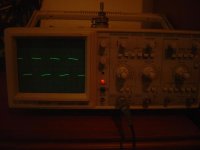
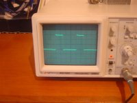
Do you have any idea why I'm having problems with the period of the square wave, when it is bigger than 18khz, and when it's smaller than 400hz.
When the square wave is smaller than 300hz the top of the square have a angular problem.
See the photo which it attached here.
The frist photo is the lower problem. And the second photo is the problem with high frequencies.
This is a circuit using a operational in comparator mode. The negative input is connected to the sinewave output, and the positive input is conected to the ground.
Best Regards,
Felipe Navarro
Attachments
Hello,
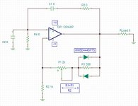
I just noticed that the schematic in post 10 is a bit unusual and has little chances to stabilize the amplitude properly. The diodes switch suddenly and the gain reduction is either too low or too high depending on the pot value.
If you want try this arrangement, it's easy. It may work better, a matched pair of diodes (like this one ) will ensure a decent symmetrical waveform.
If the pot P1 is adjusted to about 1.4k you'll get about +/-3Vpp amplitude. You can get almost any max. amplitude you want by resizing the values of R1, R2, P1 but I'll leave the exercise to you.... 😉
Let us know how it turns out.
Attachments
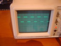
mod_evil said:Another photo.
Another information. The suppy haven't a regulator.
How about a schematic of the squarewave generator portion of the circuit?
Tilt in the squarewave is usually due to phase shift somewhere in the circuit, and the tilt here I think implies that there is LF rolloff somewhere before the 4011.
sidiy said:Hello,
I just noticed that the schematic in post 10 is a bit unusual and has little chances to stabilize the amplitude properly. The diodes switch suddenly and the gain reduction is either too low or too high depending on the pot value.
If you want try this arrangement, it's easy. It may work better, a matched pair of diodes (like this one ) will ensure a decent symmetrical waveform.
If the pot P1 is adjusted to about 1.4k you'll get about +/-3Vpp amplitude. You can get almost any max. amplitude you want by resizing the values of R1, R2, P1 but I'll leave the exercise to you.... 😉
Let us know how it turns out.
He's using a lightbulb now as is the case with classical implementations of the weinbridge oscillator. Diode clipping never seems to work well in practice although in simulations it can appear to perform ok.
Gotta lotta droop there...
It's probably there at high frequency too, you just don't notice it so much, 'cause it doesn't have time to drop so far...
Have you got a decent decoupling capacitor up close to the power and ground pins on the comparator and a reasonably stable supply?
What is the load?
w
It's probably there at high frequency too, you just don't notice it so much, 'cause it doesn't have time to drop so far...
Have you got a decent decoupling capacitor up close to the power and ground pins on the comparator and a reasonably stable supply?
What is the load?
w
kevinkr said:
How about a schematic of the squarewave generator portion of the circuit?
Tilt in the squarewave is usually due to phase shift somewhere in the circuit, and the tilt here I think implies that there is LF rolloff somewhere before the 4011.
Dear Friends,
Mine power supply is full wave retified and filtered by two 2200uf's caps, two 100uf caps and a decoupling capacitor in order of 1.5uf.
A friend called me to use to convert the sine to a square wave one 4011, but now i haven't none on the stock. I will buy someone.
The diode arrangement is a desaster! It's very problematic. I think the light bulb is better than the diode.
Best Regards,
Felipe
Drive your 4011 like this...
Look here: - Waveform Conversion.
w
An externally hosted image should be here but it was not working when we last tested it.
Look here: - Waveform Conversion.
w
wakibaki said:
In fact, you should probably read everything on the Wenzel site!
Here's a link to Wenzel's library -- as they said in the Blues Brothers "It's Glue, Strong Stuff..." http://www.wenzel.com/documents/circuits1.htm
wakibaki said:Drive your 4011 like this...
An externally hosted image should be here but it was not working when we last tested it.
Look here: - Waveform Conversion.
w
Dear Friend,
Thanks for this schematic. At the voltage divider I can use two 100k resistors. And to drive the another input of the NAND gate to High Level? What resistor do you think I can use here?
Best Regards,
Felipe Navarro
10k is a common value for a pullup, I would make R1=R2=R3=10k, this will give you an input impedance of ~5k.
100k is OK.
w
100k is OK.
w
- Status
- Not open for further replies.
- Home
- Design & Build
- Equipment & Tools
- Wien Bridge, I HATE YOU