i'm planning my diy projector, and the first thing i have to build is the lightbox, so i've to choose a bulb.
I've read in this forum that a classic spherical cold reflector with a 250W bulb and a big condenser collect about 65% of lights, so 20.000*0,65=13.000 lumens
i thing this is the only "cheap and easy" setup for a double ended lamp.
With a 150W single ended (g12) lamp i can recycle a par-30 reflector (from some spotlight) and build a setup that collect around 80-90% of the light: 13000*0.8-0.9 = 11.000 lumens.
so i have only a 2000 lumens gap with a 100W difference, so 100W less heat to dissipate.
I'm going to build a 7" lilliput projector, probably with 2 mirrors to save space.
Which bulb have i to choose? is 2000 lumens difference enought to visibly decrease brightness? are my calcolous correct?
thank you all, this forum is the best place to make something yourself!!
you left out another part!
Most people use a lamp, spherical reflector, pre-condensor lens, and then a condensor fresnel to get parallel light through the LCD.
If you want to use a parabolic reflector, then you omit the pre-condensor lens and the condensor fresnel. But you need a really big parabolic reflector so the parallel light that comes out of it lights the whole LCD. You also need to do something to block the direct light from the lamp, or you will get a very bright hot spot in the center of your image. (ie. 20 times brighter than the rest of the image!) The best way to do that is to use a small spherical reflector directly past the lamp arc. This makes the parabolic reflector design too complex and difficult to get working well.
An elliptical reflector is a much better choice. Then the light diverging from the second focal point of the ellipse goes to a condensor fresnel, as if that focal point was the light source. You can even increase the efficiency more by adding a big spherical reflector (with a hole in the middle) to send the light that missed the first time back into the elliptical reflector.
Do MH bulbs have even lumen distribution? Or (taking the lamp base to be the "south pole") do they produce higher flux near their "equator" than near their "poles"?
I guess a more specific form of my question is, what percentage of a HQI-TS 250W bulb's output lumens is concentrated into the region between the "45th parallels", north and south?
Apologies for the clumsy globe analogy
I guess a more specific form of my question is, what percentage of a HQI-TS 250W bulb's output lumens is concentrated into the region between the "45th parallels", north and south?
Apologies for the clumsy globe analogy
The short answer is unsatisfying:
Its hard to say and it doesnt matter.
I'll explain. MH bulbs have a plasma chamber that may be 5-20mm x 5-10mm. Different areas have different intensities (temps) and your optics focus on a small area throwing the rest of the light away. You hope its thrown away because it would fuzz your image otherwise. So you take steps to shut the other light out. Do you know the properties of the arc point you use? No. It depends on the bulb orientation, cooling method, etc.
Osram has a document that goes over the arc in detail. It varies quite a bit! goto their website.
So you might only use 25% of the arc. Each optic may take up 10%. The polarisation on the back of the LCD eats at least 50%. Light doesnt shine through the entire panel due to the electronic control bits ~60%? All this stuff eats that percent of all light that made it to that point so its cummulative.
25% of the arc
If I remove my LCD, and put a piece of white paper in place of the projection lens, then I can see a focussed image of the lamp's arc on the paper. In my projector, that arc image is about 60 mm long which agrees very well with the size of the lamp arc times the ratio of the two fresnels.
If you replaced the LCD with a large piece of sheet aluminum with a single hole in the center, then rays from the entire volume of the lamp arc would pass through that hole. The fresnels would still direct those rays to converge into a focussed image of the arc at the projection lens. If the hole was small, then the arc image would be dim. If the hole was larger, the image would be brighter.
When the different rays passing through such a hole are refracted by the projection lens, they all meet at one point on the screen. (Assuming you have a good lens!)
Each LCD cell acts like one of these holes. So I don't think it is possible to "use only 25% of the arc".
Sounds like you moved your fresnel closer to get the "extra light" from the rest of the arc. This is wrong. I mean no disrespect, you seem a very bright guy. Your reflector will use the light from the focus and the rest of the arc but you don't want it from the rest of the arc.
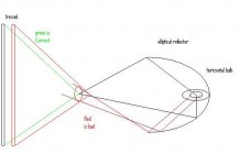
See the picture. The 2/3 of the light from the focus that hits the reflector is what you want (in black). The red light from the whole rest of the arc will make a bright circle around your focus but you cant control the vector of these rays.
If you move your fresnel closer so they are in it's imaging window you will see the whole arc chamber as you said. This reduces your contrast and softens the image. Read unfocused.
Attachments
no "magic window"
Please draw optical diagrams with the light moving left to right. That is pretty much a universal standard.
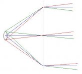
You seem to have the idea that fresnels have some kind of "imaging window" that you can use to mask unwanted rays from the ends of the lamp arc. They don't. Rays from all parts of the lamp arc will go through the fresnel. If you put the lamp arc center exactly on the central axis at the focal length of the fresnel, then light from the center of the arc will exit mostly perpendicular to the fresnel (see the blue rays in the diagram below). Light from the ends of the arc will not be be perpendicular to the fresnel, but it will still get refracted to parallel paths by the fresnel (see the red and green rays below).
Of course, rays come from every part of the arc to every point on the fresnel surface. So the drawing just shows the extremes. The light coming through every point on the fresnel forms a diverging cone. There's no way to stop it!
Every individual LCD pixel will "see" a large spot on the fresnel that consists of rays from all parts of the arc. No way to stop that either.
If you move the lamp away from the fresnel focal distance, then the cone coming through each point on the fresnel will be centered around a line that converges toward the central axis, but it will still be a cone. Move the lamp closer to the fresnel, and the cone will tilt outward, again still a cone.
Please draw optical diagrams with the light moving left to right. That is pretty much a universal standard.
You seem to have the idea that fresnels have some kind of "imaging window" that you can use to mask unwanted rays from the ends of the lamp arc. They don't. Rays from all parts of the lamp arc will go through the fresnel. If you put the lamp arc center exactly on the central axis at the focal length of the fresnel, then light from the center of the arc will exit mostly perpendicular to the fresnel (see the blue rays in the diagram below). Light from the ends of the arc will not be be perpendicular to the fresnel, but it will still get refracted to parallel paths by the fresnel (see the red and green rays below).
Of course, rays come from every part of the arc to every point on the fresnel surface. So the drawing just shows the extremes. The light coming through every point on the fresnel forms a diverging cone. There's no way to stop it!
Every individual LCD pixel will "see" a large spot on the fresnel that consists of rays from all parts of the arc. No way to stop that either.
If you move the lamp away from the fresnel focal distance, then the cone coming through each point on the fresnel will be centered around a line that converges toward the central axis, but it will still be a cone. Move the lamp closer to the fresnel, and the cone will tilt outward, again still a cone.
Attachments
This seems to be changing the subject.
Of course you can stop it. How are you stopping the rays expanding directly from your lamp that dont hit your reflector? You make a wall with a hole that limits the light to your desired cone.
I dont want the fresnel to see only the desired light, it only gets the desired light! lol And this is from a small part of the arc. Im switching to a smaller 150w G12 so a greater % of light created is used with the same system. I dont expect to lose brightness but i will see when it arrives. People with BIG arcs have missed the point of imaging optics.
When I first started I thought the structure of the lcd itself would image the light passing through so more light was better. I was wrong. You have to be precise with the light source.
So back to the original question - you use a bit of the arc. See the lamp manufacturer for the details of it. They assume an open area around it not a box with cooling design and sound damping design so your arc will be different.
ah ha!
Oh, I see now. You are talking about changing to a lamp with a smaller arc length, or using a restrictive aperature at the second focal point of an elliptical reflector. I agree that either one of those will give you a smaller light source.
When you wrote: "If you move your fresnel closer so they are in it's imaging window you will see the whole arc chamber...", I thought you were implying that you could limit the part of the arc of an existing lamp that supplied rays to the fresnel, just by adjusting the distance. Since your drawing of the elliptical reflector light engine showed the whole virtual arc image at the second focal point, I did not think you were proposing a restrictive aperature.
But I don't understand what you mean by "the structure of the lcd itself would image the light passing through"?
And I also think that lamp arcs are not all that much smaller until you get down to <5 mm, but those lamps run for so few hours and cost so much money that you might as well just buy a used commercial projector with a used-up lamp, and then put a new lamp in it. The DIY concept is to use the inexpensive 10000+ hour lamps that cost < $70 each. I use a Ushio retrofit lamp with a 24 mm arc, and I get an image so sharp I can see the individual red, green, and blue stripes within each pixel, from the center of the screen all the way to the corners. So arc length doesn't have to limit your image quality, if you have a good projection lens.
Maybe you could give us a URL for that OSRAM paper? I have never been able to find much good info on any of the many OSRAM websites.
Sure, i'll try to find it.
The title is "Technology and application
Metal halide lamps Photo Optics"
Poor wording on my part. Originally I imagined the LCD would collimate the light to some extent so that you only had to provide a strong source directly behind it.
Yes the large arc is cheap but you design the system to create a small point like an expensive bulb. You throw a lot of light away and it bugs you. oh well.
So you get that good an image without anything limiting the source to your focus. thats cool. Do you find you lose contrast or reduce the vivid colours?
Here's the link:
http://dafnwebpd.sylvania.com/idmweb/doccontent.dll?LibraryName=ecomcspd^dafnctpd&SystemType=2&LogonId=db374f5bdf141d5f7c740f0e6c6aa721&DocId=003673620&Page=1
its a 6.5Meg pdf so it may take a while if anyone is using dialup.
http://dafnwebpd.sylvania.com/idmweb/doccontent.dll?LibraryName=ecomcspd^dafnctpd&SystemType=2&LogonId=db374f5bdf141d5f7c740f0e6c6aa721&DocId=003673620&Page=1
its a 6.5Meg pdf so it may take a while if anyone is using dialup.
Thanks for the doc! That URL didn't work for me, but
http://dafnwebpd.sylvania.com/os_filenet_pages/FnDocIdDisplay.asp?docid=003673620
does. Checking it out now.
http://dafnwebpd.sylvania.com/os_filenet_pages/FnDocIdDisplay.asp?docid=003673620
does. Checking it out now.
What a great doc! Thanks me2!
Page 29 shows exactly what I was looking for. I attached a copy of the diagram on that page. It shows that for an example 575W HMI single-ended bulb, about 70% of the light falls between the 45th "parallels".
Interesting quote on page 21:
"Although only dichroic glass reflectors are being used at present, it is perfectly possible to use deep aluminum reflectors (as found in general lighting applications). They are much cheaper to produce but they have the disadvantage that, unlike dichroic reflectors, they also reflect infrared radiation, which increases the thermal load on the object illuminated".
Attachments
Yep, thats it.
There is lots of good stuff in there. So focus just inside the arc end close to the base. This puts as much as possible out of the reflector for better cooling.
And for the original post - I think you are right on to use the smaller 150w
There is lots of good stuff in there. So focus just inside the arc end close to the base. This puts as much as possible out of the reflector for better cooling.
And for the original post - I think you are right on to use the smaller 150w
contrast with long arc length
>Do you find you lose contrast or reduce the vivid colours?
No I see excellant contrast for a 350:1 LCD, and I have a DIY high gain screen, so the colors really pop.
I think the great image sharpness is because I am using a process lens that can also be used for very large format photography. It is a 600 mm fl Rodenstock APO Ronar. It is only about 65 mm in diameter, so it may actually be rejecting some of the light from the ends of the arc. (This is another place in the design that you can use an aperature to reject unwanted light.)
Thanks for the URL, and also thanks to charlie10 for the URL update.
Wow $1000 lens. Very nice. That would torpedo the rest of my parts budget.
I dont understand. Doesnt the light need to be cut off before the LCD? You have light coming around the sides of your LCD? Otherwise you chop off the edges of the picture?? I dont get it. What do you mean?
I dont understand. Doesnt the light need to be cut off before the LCD? You have light coming around the sides of your LCD? Otherwise you chop off the edges of the picture?? I dont get it.
What do you mean?process lens
$1000 lens: No actually I got it on eBay for $280. 483 mm fl process are going for much less. I got one today on eBay for $45 US! These lenses were very expensive when they were new and used all over the world for making lithography plates. Now everybody used digital instead of film. (ie. like printing plates with a laser printer), so all of these process lenses are selling as surplus.
I don't have any light coming around the sides of my LCD. Actually, the lens I use has such a wide FOV, that it was projecting small cracks I had in the frame at least 2 inches past the corners of the LCD. I had to put some tape over those cracks to get rid of the projected light streaks that appeared on the wall behind the screen.
In my last post, I was talking about getting rid of the unwanted light from the ends of the arc. If you want to do that by using a restrictive aperature, there are three possible places it could be done:
1) Masks around the ends of the discharge tube.
2) An aperature at the second focal point of an elliptical projector.
3) An aperature within the projection lens.
At each of these locations, the light is either "the object" or a formed image of the object. So you can mask out the unwanted part.

#3 is nonsensical to me. If you pass all the light through your first fresnel and LCD there is no way to seperate it out later. Thats like uncremeing your coffee. 2nd law of thermodynamics - 3rd form:
In any thermodynamic process that proceeds from one equilibrium state to another, the entropy of the system + environment either remains unchanged or increases.
You must put a hell of a lot of energy into unmixing your image from the various arc points...
#1 right at the bulb is crazy for other thermodynamic reasons. ala kiss your bulb goodbye.

The light focus (2nd) is the only point. 😀
The following is my longwinded take on what's up with the lamp arc. I feel I'm beginning to really understand it. I'm still missing on why we can't use an even bigger lightsource, eg. a compact fluorescent bulb.
If I understood it better, I might be able to express the same concept in much fewer words. But I don't, so here goes.
Assuming a 220/330 split fresnel config, and ~20mm lamp arc.
1. Perfect light
The light coming from the exact focus of the rear fresnel is the most "perfect" light. This light gets collimated pretty much perfectly by the rear fresnel, is colored by the LCD, and refracted by the front fresnel to a tiny point. No projection lens is necessary for this light. This light can be projected onto a screen of any shape and tilt at any distance, and it will form an image that will stand out in perfect crisp focus, whether that screen is at 1 foot or 100 feet from the projector.
2. The rest of the light
Unfortunately there is very little of this light. If we limited ourselves to this perfect light (eg. via masking the discharge tube) the image would be crisp but very very dim.
To get a brighter image, we use the rest of the lamp arc. Many angles of light, from all points on the arc... basically _everything_ that hits the rear fresnel!
Since this light is not coming from the fresnel focus, the fresnel cannot perfectly collimate it. I estimate it has a beam spread of about 3 degrees. For a diagram of this, see post #7. Why are we allowed to have such a wide beamspread? We'll get to that later.
3. The LCD
The LCD does little more than color and polarize this light... it doesn't refract or diffuse it. The light continues in the same direction, with the same beamspread.
The light from each pixel emanates now in a ~6 degree wide cone, instead of a tight beam. These pixel-cones certainly overlap each other. A piece of paper held right in front of the LCD would show a legible image, but moving that piece of paper even just 20mm farther would show an illegible blur. Each point on the piece of paper would be lit by about 40 pixels, about as many as are in an "x" character on my laptop here...
4. Front fresnel
The front fresnel refracts the cones towards that fresnel's focus. In fact at the focal point of the front fresnel, the cones overlap each other almost completely, in a volume roughly 330/220 times the size of the lamp arc, centered around the focus. This is the "lamp arc image". Basically, the two fresnels act to form an upside-down image of the lamp arc at the focal point of the front fresnel.
5. The other lens
If this light is allowed to continue onto a projection screen, it wil show a very very blurry image of the LCD. Basically an incoherent mess. No good. As you said, cream in the coffee. But... (continued)
(continued)
... But there is a device which can accomplish the task of unmixing the image from the various arc points. It's simply a convex lens. Its basic function is to image, aka separate the cream from the coffee. By focusing it on the LCD and on the screen, it essentially unmixes the image.
So... what's up?
Yes, this is a big concept, inviting consultation of the ancient masters.
6. Back to DIY projectors
Those renaissance dudes used a lens to image a large outside scene onto a small surface. Overhead / DIY projectors use the same basic concept to image a small surface onto a large plane, the projection screen.
The projection lens is what allows us to move away from a point source lamp. IF we sign up for worrying about focus, AND we fork over some cash for a decent projection lens, THEN we can start using a bigger lamp.
The projection lens focuses (literally) on two things: the LCD panel, and the projection screen (which is at some "throw" distance in front of the lens). This is different from the fresnels, which focus on the lamp arc and on the lamp arc image. The interplay between these two optical systems is what makes the projectors work so well.
For now, let's ignore the lamp arc, and just think of an individual pixel-cone. For any given pixel on the panel, all rays of light emanating and passing through the projection lens will wind up at a single point on the screen. Put another way, the projection lens will take the cone of light from the given LCD pixel, and squeeze it back down to a point on the screen. As long as the LCD and the screen are the same shape (presumably, "flat") and the focal length of the lens is appropriate, the lens is able to do this for every pixel of the LCD. The cone-points will all line up right next to each other, forming perfectly non-overlapping pixel-images on the screen. Perfect crisp image, just like in part 1) above, but now much brighter.
However this lens is expensive to manufacture. So again we compromise, and use a cheaper lens. This lens doesn't focus each pixel to a point; instead to a small splotch. It introduces aberration. The splotches overlap slightly. This translates to a less crisp, lower contrast image... but brighter, and cheaper.
7. Irising
A basic rule of thumb I remember from manual photography: if it's bright outdoors, you can get away with decreasing the aperature, increasing depth of field and making focusing easier.
After thinking (and yammering) about DIY projectors, now I understand better what is happening in the camera. The camera aperature is making the light-cones from my subject tighter, more precise, and dimmer.
Trying to refer back to post #17: 1) reducing the size of the lamp arc will reduce the angular extent of the pixel-cones, decreasing the overlap of the splotches and increasing crispness... but either at the expense of brightness, or at the expense of a pricier lamp. and 3) Placing an iris (black screen with a hole punched) at the lamp arc image will also make the pixel-cones tighter, with the same effect.
Employing a collimating LCD, if such a thing were common (perhaps via an LCD "privacy screen"?) should have a similar effect. Better focus, less light. I think this is similar to a "louver" in a theatrical spotlight.
... But there is a device which can accomplish the task of unmixing the image from the various arc points. It's simply a convex lens. Its basic function is to image, aka separate the cream from the coffee. By focusing it on the LCD and on the screen, it essentially unmixes the image.
So... what's up?
Yes, this is a big concept, inviting consultation of the ancient masters.
An externally hosted image should be here but it was not working when we last tested it.
(http://www.thebigcamera.com.au/obscura.html)Since ancient times it had been observed that light entering through a small hole in the wall of a darkened room casts an inverted image of the scene outside on the opposite wall.
In 1558 the Italian physicist Giovani Battista della Porta described the use of a convex lens in the hole in the wall to improve the brightness and clarity of the image.
(http://www.acmi.net.au/AIC/CAMERA_OBSCURA.html)Porta's second edition of Magia Naturalis (1591) includes a lens for the camera. This had been suggested earlier by Roger Bacon, and was in use by others in the 16th century.
6. Back to DIY projectors
Those renaissance dudes used a lens to image a large outside scene onto a small surface. Overhead / DIY projectors use the same basic concept to image a small surface onto a large plane, the projection screen.
The projection lens is what allows us to move away from a point source lamp. IF we sign up for worrying about focus, AND we fork over some cash for a decent projection lens, THEN we can start using a bigger lamp.
The projection lens focuses (literally) on two things: the LCD panel, and the projection screen (which is at some "throw" distance in front of the lens). This is different from the fresnels, which focus on the lamp arc and on the lamp arc image. The interplay between these two optical systems is what makes the projectors work so well.
For now, let's ignore the lamp arc, and just think of an individual pixel-cone. For any given pixel on the panel, all rays of light emanating and passing through the projection lens will wind up at a single point on the screen. Put another way, the projection lens will take the cone of light from the given LCD pixel, and squeeze it back down to a point on the screen. As long as the LCD and the screen are the same shape (presumably, "flat") and the focal length of the lens is appropriate, the lens is able to do this for every pixel of the LCD. The cone-points will all line up right next to each other, forming perfectly non-overlapping pixel-images on the screen. Perfect crisp image, just like in part 1) above, but now much brighter.
However this lens is expensive to manufacture. So again we compromise, and use a cheaper lens. This lens doesn't focus each pixel to a point; instead to a small splotch. It introduces aberration. The splotches overlap slightly. This translates to a less crisp, lower contrast image... but brighter, and cheaper.
7. Irising
A basic rule of thumb I remember from manual photography: if it's bright outdoors, you can get away with decreasing the aperature, increasing depth of field and making focusing easier.
After thinking (and yammering) about DIY projectors, now I understand better what is happening in the camera. The camera aperature is making the light-cones from my subject tighter, more precise, and dimmer.
Trying to refer back to post #17: 1) reducing the size of the lamp arc will reduce the angular extent of the pixel-cones, decreasing the overlap of the splotches and increasing crispness... but either at the expense of brightness, or at the expense of a pricier lamp. and 3) Placing an iris (black screen with a hole punched) at the lamp arc image will also make the pixel-cones tighter, with the same effect.
Employing a collimating LCD, if such a thing were common (perhaps via an LCD "privacy screen"?) should have a similar effect. Better focus, less light. I think this is similar to a "louver" in a theatrical spotlight.
- Status
- Not open for further replies.
- Home
- General Interest
- Everything Else
- The Moving Image
- Lighting and OHP
- wich bulb? HQI-TS 250W+spherical or HQI-T 150W+par30?