I had always this same problem each time I refurbished a crossover... sometimes here it is sensible up to 0.047 uF. Playing with 0.1 uF is more than enough.
As AllenB said : try to find the value that suits you best by // caps then try to find one with the near value to have not too much cap and change the ESR too much (film caps have a low resistance VS lythics and the more you // caps the more you lowish its resistance ... which may be good or bad as already told a good designer designs with such parameters). We can imagine 16 or 18 uf being not a too big value they could have chosen a film cap and maybe add a serie resistor for the damping in spite of the standalone lythic cap... but you never know, so the best is to find it yourself with ears here !
Solen/SCR works fine in that area // with the driver. TlHP.com have a large panel of SCR mkps with precise measurement : 1 uF ; 0.22 ; 0.3 ; 1.6 ; 0.5uF, etc...
Your Proac will be setuped better than in the factory and to your likings. Do not move the values of the high pass caps or the low pass coil.
Yo can not know what wanted to do Proac as you have not measured that cap when brandnew... The best is to work around the values you see on the cap and your measure and find the in-between that works best for you. We told you before in the other thread than you can not believe what exactly is marked on a lythic cap... for all the reasons members have pointed out.
16 to 18.5 uF is a little job... It is more borring when you have bigger values in the 100 or 700 uF for illustration !
So 16 // to 1 // to 0.5uF = 17.5 uF and so on. Not a great job and easier when the filter is outside as we told.
Last edited:

What do you mean for me not to move the value of the high pass caps and low coil?
you mean not to play a little with the 8uf cap on the tweeter circuit?
and don’t mess with the inductor on the woofer? I don’t plan on messing with the woofers inductor no.
but I do plan on playing with the 8uf cap on the tweeter.
here is the xo in case you didn’t see it.
and btw thanks so much for your help.
Attachments

Galu, because you know OP the best, it should be you who tells him about his inductor cores.He's a musician, not a scientist!
But if you want to re design the filter, why would you change it ? You have just to find the precise capacitance of the Alcap value to have the good XO cut-off.
Look the coil, it is unwinded to have a precise value too.
This is not a gogo filter, what you have to do is just to find the precise Alcap value with your ears ! Easy 🙂
Look the coil, it is unwinded to have a precise value too.
This is not a gogo filter, what you have to do is just to find the precise Alcap value with your ears ! Easy 🙂
The advantage of making your extra tonal adjustments outside the crossover is that you don't change the relative interaction between the two ways. Their relative contribution is of course the main function of the crossover. You can change one in the crossover without affecting the other, but it is more difficult.
Galu, because you know OP the best, it should be you who tells him about his inductor cores.
I already discussed inductor cores with tone? on one of his other threads regarding his ProAc DT8s.
This one: Do crossover designers take DCR into account in their designs?
I already discussed inductor cores with tone? on one of his other threads regarding his ProAc DT8s.
This one: Do crossover designers take DCR into account in their designs?
everybody has moved on and you are still trying to point out all my stupidities.
do you understand why I don’t pay attention to any of your advice?
just ignore me man.
The increased capacitance on the woofer(s), without changing the coil, increases the crossover frequency slightly, and also makes the crossover steeper. The frequency response will have a slight bump up below the on axis acoustic crossover point, and a slight droop down above.
Lower frequencies are "slower", but the woofer's speed hasn't changed 😉
The change also affects vertical polar pattern, peaks and nulls will be directed at slightly different angles.
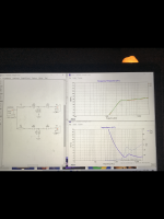
Using this calculator, which allows substitution of individual part values:
https://speakerwizard.co.uk/1st-and-2nd-order-crossover-calculator-and-response-simulator/
And with no idea of the your speakers actual crossover point or type (BW or LR), ran a few examples.
Though the examples assume fixed impedance and inductance for the drivers through the crossover region, (usually not valid), they do indicate little change from a 16 (design goal) to an 18.46uF woofer capacitor value.
Doubling the value to 32uF makes the slight difference in what you are hearing more apparent.
View attachment 1067250View attachment 1067251View attachment 1067252
Anyway, interesting to see what the "wrong" values might do.
Art
Hey Art thanks for taking the time explaining this to me.
yeah I read up on some of the stuff to make more sense out of it.
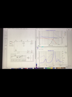
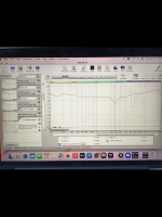
My xo looks more like the attached file.
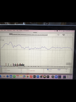
Also attached is a measurement of my speakers ( with the 18uf value in there) at a close up measurement. I’m assuming my XO is at around 2.5khz.
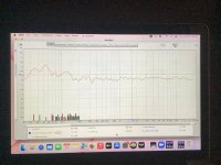
thing is that on axis in my seating position the freq response is pretty flat. Other than that I get a bit of a BBC dip from 1.5khz to 3khz off axis
one attachment is on center at my listening position and the other is about half a foot or so up. So you can see what I am talking about.
the speakers are an MTM design.
i was thinking of maybe ‘ filling in that BBC dip ‘ by making some changes to the xo values and see how it sounds. Maybe I like the BBC dip.
don’t know
Attachments
The advantage of making your extra tonal adjustments outside the crossover is that you don't change the relative interaction between the two ways. Their relative contribution is of course the main function of the crossover. You can change one in the crossover without affecting the other, but it is more difficult.
sorry Allen What do you mean by outside the crossover?
why are you sending me a link with no prior explanation of what I am looking at and why ?
i have no context of the link or what I should be looking for.
and then some of you guys wonder why I ignore you. Or tell you to ignore me.
sheesh.
Last edited:
That is a preferred series, and the cap is within tolerance, can't sue the maker.
Swap your speakers around, see how it changes the effect..
And do give us your room treatment, what is on the walls whether speakers are in a corner, and so on.
Or take wires out, and use that to check with different capacitors in parallel to adjust the sound to your taste.
Old tuning gang from radio is also useful, as a variable cap.
Once satisfied, put it inside the box.
Also, baffles, damping material and so on can be adjusted.
Have fun.
So you make your filter with 20 % tolerance at the cut-off ? And you think Proac does so ?
Nah. Whatever the value measured is good or the cap has drifted if old, it worths a brandnew as a BP lythic has more and more leakage when it olds... imho.
Nah. Whatever the value measured is good or the cap has drifted if old, it worths a brandnew as a BP lythic has more and more leakage when it olds... imho.
So you make your filter with 20 % tolerance at the cut-off ? And you think Proac does so ?
Nah. Whatever the value measured is good or the cap has drifted if old, it worths a brandnew as a BP lythic has more and more leakage when it olds... imho.
is that directed to me?
i don’t know if Proac made the xo to have a 16uf cap which is +%10% and is over that. The speakers are only 2.5 years old. Of course I don’t know how old the capacitors are. If they had them lying around or something.
i do know that I prefer the 18uf current measurement of the cap versus the 16uf which is printed on the label.
tomorow I will get a couple 2uf caps and put them in parallel with the 16uf to make 18uf and see how they sound compared to the electrolytics that were in there as an experiment.
ProAc DT8 are fairly expensive loudspeakers, so markbakk is right. Capacitors are selected based on actual measurement and, by design, they should be 18 uF. Though, I’m still surprised to find electrolytic capacitor at any xover position, considering DT8 price.
ProAc DT8 are fairly expensive loudspeakers, so markbakk is right. Capacitors are selected based on actual measurement and, by design, they should be 18 uF. Though, I’m still surprised to find electrolytic capacitor at any xover position, considering DT8 price.
well they are proacs entry level speaker for their response line.
but then again think of the space a 16uf or 18uf poly cap would take on that small board. And the cost would be quite different.
my initial ’ experiment ‘ was to see if I could hear the difference between the electrolytic in there and a poly cap. Little did I know that it didn’t measure at 16uf but 18uf.
and to your point and markbakk. I don’t think that both caps would measure 18uf by accident if they drifted. What are the odds.
Whatever the case may be. I will try a value of 18uf there in poly where the electrolytic was and decide by my ears.
i much prefer the 18uf value there to the 16uf
i much prefer the 18uf value there to the 16uf
I always err on the side of rather having a dip in the response than a peak when refurbing oem crossovers. I dont lose sleep over anything less than 10% tolerance, erring on the side of a slightly bigger spread at the crossover point, so there's less peaking. What matters more IMO is channel balance, so matching both L/R components in pairs is a must.
On the tweeter HP it will depend on how the lower portion of HF sounded when driven harder. The peaking of response and the resulting impedance dip indicates a higher filter Q (not desirable when the HP is already close to tweeter Fs, needing more electrical dampening). Most factory tweeters have a high Qts and HP point closer to Fs. This IMO is the most important area to concentrate efforts, mainly because its the greatest contribution and influence on listening fatigue.
Just switching the HP series cap(s) for better quality same value film/foil PP often smooths out the tweeter by a significant amount, even when coming from a polyester or mylar film cap. The different dialectric characteristic alone can have alot of affect on how well the HF integrates to the rest of the speaker or in the worst case it ends up drawing attention to itself. Multiple series caps in higher order HPs can make this effect even more pronounced, especially when the speaker was already on the brighter sounding side. In this case the HF will have to be padded a little more, allowing better upper HF response extension with a smaller parallel cap across the series padding R if need be. The danger is going too far here, making the treble sound etched and accentuating amplifier hiss. Many tweeters don't respond well to upper treble lift, mainly because they've already been designed to operate with increased HF diaphragm breakup to lift and flatten upper treble. Further increasing extreme HF just adds hash and artifacts. Our ears aren't as sensitive to this area but we can easily tell the difference in tonal balance of the speaker as a whole.
I find most smaller 2 way speakers don't have enough BSC, mainly because manufacturers don't like the increased cost of extra copper in the LP series inductor. That results in a shouty and congested sounding design and needs placement close to a wall to compensate. More BSC also means lower efficiency and that can trick people into buying the louder sounding speaker when comparing them in an A/B listening scenario.
I always err on the side of rather having a dip in the response than a peak when refurbing oem crossovers. I dont lose sleep over anything less than 10% tolerance, erring on the side of a slightly bigger spread at the crossover point, so there's less peaking. What matters more IMO is channel balance, so matching both L/R components in pairs is a must.
On the tweeter HP it will depend on how the lower portion of HF sounded when driven harder. The peaking of response and the resulting impedance dip indicates a higher filter Q (not desirable when the HP is already close to tweeter Fs, needing more electrical dampening). Most factory tweeters have a high Qts and HP point closer to Fs. This IMO is the most important area to concentrate efforts, mainly because its the greatest contribution and influence on listening fatigue.
Just switching the HP series cap(s) for better quality same value film/foil PP often smooths out the tweeter by a significant amount, even when coming from a polyester or mylar film cap. The different dialectric characteristic alone can have alot of affect on how well the HF integrates to the rest of the speaker or in the worst case it ends up drawing attention to itself. Multiple series caps in higher order HPs can make this effect even more pronounced, especially when the speaker was already on the brighter sounding side. In this case the HF will have to be padded a little more, allowing better upper HF response extension with a smaller parallel cap across the series padding R if need be. The danger is going too far here, making the treble sound etched and accentuating amplifier hiss. Many tweeters don't respond well to upper treble lift, mainly because they've already been designed to operate with increased HF diaphragm breakup to lift and flatten upper treble. Further increasing extreme HF just adds hash and artifacts. Our ears aren't as sensitive to this area but we can easily tell the difference in tonal balance of the speaker as a whole.
I find most smaller 2 way speakers don't have enough BSC, mainly because manufacturers don't like the increased cost of extra copper in the LP series inductor. That results in a shouty and congested sounding design and needs placement close to a wall to compensate. More BSC also means lower efficiency and that can trick people into buying the louder sounding speaker when comparing them in an A/B listening scenario.
whats BSC?
good info on the HP caps. Appreciate it
thanks
- Home
- Loudspeakers
- Multi-Way
- Why would a manufacturer use a 16uf cap that is really 18uf?