For tube amps I use Spice just as a proof-of-concept e.g. to verify the operating points. Using Spice to optimize distortion of tube power amps is more or less meaningless as tube models and especially output transformer models are far from reality. And the variation between tubes of same make can be significant.
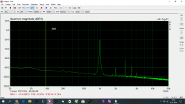
E.g. for the SET in post #55 Spice predicts 1.5% THD at 1W. This is more than 20x higher than reality in this case (about 0.05% THD).
E.g. for the SET in post #55 Spice predicts 1.5% THD at 1W. This is more than 20x higher than reality in this case (about 0.05% THD).
All that is being said here is that plotting a loadline using Spice data means there is not a simple 1:1 inverse correlation between voltage and current. That'd be expected for an inductive load as Spice measures data in the time domain and an inductor is not a simple resistive load as the amount of current flowing changes.
Whilst it'd be lovely to correlate observations like this to real world perceived sound quality, none were implied.
kind regards
Marek
Whilst it'd be lovely to correlate observations like this to real world perceived sound quality, none were implied.
kind regards
Marek
cancellation across the spectrum
Does the cancellation occur at other frequencies with the tuning you did for 1khz at 1 watt? Will you post the distortion at other frequencies?
Steve
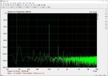
I did some THD tuning on my breadboarded NFB SET (shown here Corona: An Ultra-Low Distortion A2 DHT SE Amp Prototype). There is quite a lot of distortion cancellation going on between stages and output transformer. THD and distortion profile can be "dialed-in" by adjusting the driver pentode's screen resistor (R18 in the schematic).
Here is the result for 1W. Even at 5W (close to max power) THD is about 0.5%.
Does the cancellation occur at other frequencies with the tuning you did for 1khz at 1 watt? Will you post the distortion at other frequencies?
Steve
Does the cancellation occur at other frequencies with the tuning you did for 1khz at 1 watt? Will you post the distortion at other frequencies?
Steve
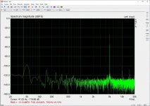
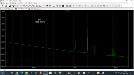
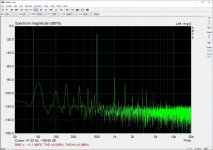
The cancellation seems to occur at other frequencies as well. Here are graphs of 1W at 500Hz and 5kHz. Note that these are measured with one of the better E130L tubes in my stash. Some have much higher distortion in this SET even though they measure almost 100% with AVO.
I haven't measured the output impedance but according to Spice it should be around 1.4 ohm so DF is about 5. And all this is without global feedback. Adding GFB seems to make things much worse with added higher order distortions as Baxandall pointed out years ago.
Attachments
I believe there was no simulation software for the Wright brothers to use to design their airplane.
Draw an ellipse that straddles evenly around that load line, and at the same slope.
Now analyze the degree of uneven spacing of the grid voltage lines, first along the top half of the ellipse, then analyze the uneven spacing of the grid voltage lines along the bottom half of the ellipse.
That is a good representation of the amplifier distortion into a loudspeaker that has a reactive impedance (like most all loudspeakers have at lots of different frequencies).
Thanks 6A3sUMMER, sorry for the elementary question, but what determines how wide is the ellipse? Higher damping make it tighter? Then of course speakers with huge variationin impedances on the audio spectrum will make it even worse.
Am I right saying that triode is the less sensitive to this ellipse-thd variation, pentode the most sensitive (hitting the knee with the loadline), and UL with its wider knee is inbetween the two.
Many simulations had been done with the Boeing 737 Max airplane, a jet that continously flies in a state in which it needs assistence in stabilization from a computer programm. Otherwise, it wouldn't be able to fly in a stable state of its own.I believe there was no simulation software for the Wright brothers to use to design their airplane.
Last edited:
What is happening at the left side of the fundamental 500Hz?The cancellation seems to occur at other frequencies as well.
Relative high peak at 50Hz, is it interaction with the mains or a supply ripple?
Attachments

What is happening at the left side of the fundamental 500Hz?
Relative high peak at 50Hz, is it interaction with the mains or a supply ripple?
I think it is partly related to me using Pete Millett's Soundcard interface where the input voltage ranges do not quite fit the soundcard in this case. The load is a 6.8 ohm resistor so 1W is about 2.6 Vrms. The previous graph was with 20V range. Here is the same with 2V range (so actually slightly overloaded). Another cause for 50Hz related spuries is probably my breadboard setup and AC heating.
Attachments
Software and airplanes do not always fit together well.
A couple of new design 737 Max had serious crashes.
There was software, there was hardware, and there were operators who did not know much about the software/hardware combined system.
A system with a single sensor for important data has a problem if it fails.
A system with dual sensors for important data has a problem if one of them fails (which one is right?
A system with triple sensors might be better, might not. Increasing the number of parts increases the chance of one going bad, especially if software is not sure.
If the hardware has any kind of problem, software is not always the solution.
I once worked on a project with weekly Monday morning project updates listing problems.
Software types said Hardware should fix the problem.
Hardware types said that Software should fix the problem.
Some problems did not get fixed before the product was released.
The 737 Max was not the first problematic design in the Seattle Tacoma area.
Perhaps the Tacoma Narrows Bridge was.
zintolo,
I believe that for an amplifier without negative feedback, that generally the ellipse is more of a linearity problem for a single ended triode amplifier, than it is a linearity problem for a push pull triode amplifier.
I hope that partially answers your question.
I will leave it to other posters to give more comments for other amplifier configurations and operating modes, regarding your question in Post # 67.
- Home
- Amplifiers
- Tubes / Valves
- Why we need to check on the harmonics and THD?