Can't remember details of this study, but the result was that the brain tries to dictate something which had to be logically better and the feelings about that could be really the opposite of that.
It could describe this "the better the measurements, the better the sound must be" dogma of the print magazines...
Thanks for the interesting explanation. Personally I tend more to the party of the low noise low distortion.
There are things that I just cannot tolerate such as the presence of secondary peaks not present in the test signal ... or in the absence of signal a high noise floor Unacceptable I tolerate more some kind of distortion than noise
As for the 3D effect, many swear that it mainly depends on the interction between the listening environment and speakers.
A normal system in an acoustically great room will sound very 3d, if this effect has been captured by the recording of course.
For example, now that I work from home I am impressed by the image I get when listening to the computer system ... I am practically litening from one meter away from the speakers and the sound comes completely from the screen ... an impressive thing As if the screen had its own own speaker which obviously does not have
I guess this happens because the interactions with the room are limited ? less reflected sound ? (we "hear" a wall when the wall reflects the sounds. Put a blanket on it and the wall will go down ... acoustically i mean)
Unfortunately I don't have a listening environment that allows me to make serious comparisons and evaluations. And I'm very sorry about that
Speaking of the tubed Studer ...
The RecorderMan
were the consoles tubed too? Do the new solid state Studers sound really so bad ?
some of the very best preamp in the world are solid state
Like the John Curl Blowtorch preamp for instance
P.S. by curiosity i have downloaded the C37 service manual ... just to peep inside
I see a lot of interesting schematic but i am not an expert
Last edited:
Studer C37 was a taperecorder with only very few diodes and transistors in the power supply. Signal path is fully tubed. Personally I can only speak about A77/B77 and Studer A810, which are great machines but even the differences in the audio cards (Revox uses discrete audio amps, my Studer has integrated amps) are audible. Thats the problem, when everything at one point of the evolution of equipment become audible, some things sound nicer and some don't. Its not about bad or good, its about the best and the second best sound. I love the sound of my A810, but one day I may own a fully tubed model and don't know what happened then. Its good not to know. But my feelings about tube in audio is, that they are able to deliver things that transistors fail to compete with. Its not just the smoothness, its a lot more. But many of those sound effects may be not measureable, too.
I think with speakers and acoustics that both, the speaker and the room, should fit each other. A good room is a properly damped one. There are strange effects happen when the speaker is tuned to a room. Its a longer period of playing time necessary, but at one point both have adapted to each other, their acoustical resistance is optimized to sound best in this room. Move the speaker to another room and the procedure starts newly.
Acoustical stage image and 3D highly depends of the speakers ability to keep those informations intact instead of destroying them. The speaker makes or can break most of those effects, contained on the recording.
Btw, the best preamps I heard were tubed gear. Transparent, fast, unstressed, relaxed, depp 3D sound, never boring but quite involving into the music. I would call them "sound machines" rather than zero THD reproducers. True in the sense of a fully believable acoustical illusion.
Last edited:
One more point I would like to say. When the power amplifier is with low distortion, it truly reflects the performance of the preamp and signal source.
I finished repair of the Matisse reference line amp for a friend yesterday. I repaired it few years ago and it didn't sound right to me at all. When I hear it again yesterday with use of my 300B mono power amplifier, it sounds so beautiful.
My friend came over for audition in the afternoon. He was very impressed how good it sound. He enjoyed so much and listened to the music about 3 hours.
Anyway, I believe low distortion is way to go. Once you want having some distortion in the equipment, we will get lost because there's no standard to aim for.
p.s. The Matisse reference line amp THD was measured at 0.06% by Soundcard Scope.
Last edited:
I don't think you can associate tube amps with low distortion yet many prefer the sound compared to a very low distortion solid state amp. It seems that some even order distortion is quite pleasing?
Studer C37 was a taperecorder with only very few diodes and transistors in the power supply. Signal path is fully tubed. Personally I can only speak about A77/B77 and Studer A810, which are great machines but even the differences in the audio cards (Revox uses discrete audio amps, my Studer has integrated amps) are audible ...
Hi ! i confess your words have triggered my curiosity. I downloaded the service manual of the C37 available on line for free
STUDER C37 SM Service Manual download, schematics, eeprom, repair info for electronics experts
and even being everything but an expert i think that C37 tube circuits are very interesting ... and this video as well
Gotham Audio Studer C37 - YouTube
May i ask you details about your playback system ? the electronics i mean
Yes ... that effortless sensation provided by tubes is very addicting
I am thinking to go hybrid because i think that tubes are best at Vgain
Thanks a lot, gino
Many tube pre has less then 0.01% dist.I don't think you can associate tube amps with low distortion yet many prefer the sound compared to a very low distortion solid state amp. It seems that some even order distortion is quite pleasing?
As for power amps less then 0.1% is not uncommon
True, and tube quality is not coming from percent point differences. High voltage has its merits.
Hi ! interesting point Could you please elaborate a little more ? thanks a lot, ginoTrue, and tube quality is not coming from percent point differences. High voltage has its merits
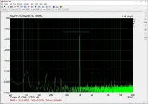
Here is the measurement of THD for my 300B mono without NFB after fine tuning.
0.5W 0.1%
1.0W 0.21%
2.0W 0.48%
8.0W 2.88%
0.5W 0.1%
1.0W 0.21%
2.0W 0.48%
8.0W 2.88%
Last edited:
Impressive. But nobody can judge how it sounds after those measurements.
WE stated the dB's of second and third harmonics. That would say something more in detail about the sound, but still isn't the complete picture.
No great wine can be judged by its chemical analysis.
No optical lens quality can be judged by its optical parameters.
No new car design can be judged by its digital brother alone. Real driving is necessary.
The same applies to all electronic gear.
And to audition itself couldn't be described in an audio forum.
Its an experience someone has to do for himself, because its highly subjective.
So your numbers are fine, but they don't mean anything.
Whats the damping factor of your amp and in combination with what speakers are they being used? Seems to be equally interesting.
Last edited:
Its about resolution in high energy/ high voltage amp systems. Makes for much more convenient and smart/ listenable PSU and circuits compared to SS technology. What we listen to is stored energy in electrical systems.Hi ! interesting point Could you please elaborate a little more ? thanks a lot, gino
Do you mean measuring the distortion in the current? Voltage amps are pretty impervious to voltage being changed by the load, but the load current is down to the nature of the load, and that's an interesting point, but its all about the speaker, not the amp.Is all THD and IM testing done with a non-inductive power resistor?
What about using a real load, like the Elliptical load of an actual loudspeaker?
I think that might make the THD and IM distortion worse in some cases.
And, the distortion will be much more variable versus the frequency of the test tone(s).
If you want to charaterize the amp + speaker combination you might as well stick a measurement microphone in front of the speaker and include the mechanical non-linearities too. (In an anechoic chamber of course).
Modern systems endevour to separate out the components of the system to make things more controllable - measure the voltage output of the amp, measure the speakers performance given a known voltage input. The moment you start lumping these together you lose sight of the convenience of any amp being able to drive any speaker.
Of course with class D output filters there's a definite interaction with the load that's often swept under the carpet, and this is a case where measuring the voltage distortion at the output (of the filter) under a true loudspeaker load is going to be illuminating and I think you are making a good point particularly for such a set up where the output impedance of the amp is a lot more than milliohms. (and its the motivation for overall feedback loops are often added around the filter)
And the same applies to many valve amp designs, for similar reasons (non linear magnetic components in the amp output circuit).
I did not say that testing with a real loudspeaker load is easy.
That is up to you.
I am just saying.
Mark Tillotson,
I am sorry, I did not make my statement in my earlier post very clear.
And I am wondering, did I miss the point(s) you were making in your post?
Draw a straight resistive loadline on the plate curves of your favorite output tube type.
Now analyze the degree of uneven spacing of the grid voltage lines. That is your distortion into a resistive load.
Now, draw an ellipse that straddles evenly around that load line, and at the same slope.
Now analyze the degree of uneven spacing of the grid voltage lines, first along the top half of the ellipse, then analyze the uneven spacing of the grid voltage lines along the bottom half of the ellipse.
That is a good representation of the amplifier distortion into a loudspeaker that has a reactive impedance (like most all loudspeakers have at lots of different frequencies).
You almost certainly will have 3 different amounts of distortion:
Top half of the ellipse
Bottom half of the ellipse
Straight load line.
And the winner for lower distortion usually is the straight load line (non-inductive load resistor).
If the straight load line is not the lowest of the 3 distortions, then the tube requires a more optimal load line.
Amplifiers need to be designed to take a signal in, amplify it to a higher power out, and then to drive a loudspeaker.
That means that this is part of a system. The amplifier design should not be done as a project in isolation (no regard for the input signal driving impedance, voltage level; and no regard for the loudspeaker load it will have to deliver power to.
But of course, if we apply global negative feedback, then we can reduce the distortion of both the straight load line, and of the elliptical load line.
Danger: If the amplifier negative feedback is not designed properly, then the amplifier may go unstable when it drives the reactive loudspeaker impedance.
Lots of negative feedback and non-inductive load resistor is not the same as Lots of negative feedback and a reactive loudspeaker impedance.
The above applies both to tube amps with output transformers, and it applies to tube amps that are without output transformers (OTL).
I hope that clarifies the difference between an amplifier driving the simple non-inductive resistor, versus driving many (most?) real world loudspeakers.
Oh, I was talking about Vacuum Tube Amplifiers; not Solid State amplifiers; and not about Class D amplifiers of any solid state output device.
This is the Tubes /Valves portion of this Forum.
Last edited:
I will afford to make a claim that there are Universe standarts to aim for. Ideomotor action, it basically is determined by environment and desire/interest to fit it, to know it, to learn it. And if you recognize Universe by scheme of quadrants, where space is affected by it's time and proportionality, you won't be ignorant about peroformance of your parts being made from same stardust. Then you will learn its favour in flavour. Like every component is a small pet or child, that loves certain behaviour. And wants you to play with it. I talk to my trannies a lot. I dream with my tubes.
Here is the measurement of THD for my 300B mono without NFB after fine tuning.
0.5W 0.1%
1.0W 0.21%
2.0W 0.48%
8.0W 2.88%
I did some THD tuning on my breadboarded NFB SET (shown here Corona: An Ultra-Low Distortion A2 DHT SE Amp Prototype). There is quite a lot of distortion cancellation going on between stages and output transformer. THD and distortion profile can be "dialed-in" by adjusting the driver pentode's screen resistor (R18 in the schematic).
Here is the result for 1W. Even at 5W (close to max power) THD is about 0.5%.
Attachments
Hi and thanks a lot for the valuable advice. Actually the energy stored in a capacitor is =1/2*C*V^2Its about resolution in high energy/ high voltage amp systems. Makes for much more convenient and smart/ listenable PSU and circuits compared to SS technology. What we listen to is stored energy in electrical systems.
So doubling the working voltage makes the energy 4 times bigger
Still i have another feeling ... when i look at tube designs i see few active devices.
Instead i have a solid state line stage with more or less 20 active parts. Is this complexity really needed ? i do not know.
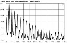
Speaking of distortion i am attaching an interesting case of 300B amp taken from here
Jadis SE300B monoblock amplifier Measurements | Stereophile.com
and all at 1,6W into 4 ohms !!!
i am quoting the listening impressions in the article
I know I'm in front of something special when equipment under test demands a reevaluation of my entire relationship with music and its reproduction in the home. This, the Jadis SE300Bs in conjunction with the Jadis Eurythmies have done. I don't know what it all means yet—we'll see what happens when I go back to push-pull after the Audio Note Kasai review up next. These are interesting times.
wow ....
Anyway ... i would be curious to listen the Jadis Eurythmies powered with another amp. Very curious ... very
Attachments
Last edited:
Now, draw an ellipse that straddles evenly around that load line, and at the same slope.
Now analyze the degree of uneven spacing....
You almost certainly will have 3 different amounts of distortion:
Top half of the ellipse
Bottom half of the ellipse
Straight load line.
And the winner for lower distortion usually is the straight load line (non-inductive load resistor).
Interestingly, looking at an output tube into a transformer, when modelled in Spice, it is possible to plot out the current/voltage back onto the paper loadline.
What you see is an upward slope in the line at low voltage/high current and also that the line is actually a very flat figure of eight bow-tie.
The outbound journey to maximum signal strength doesn't come back along the same trajectory but loops back through the bias point to complete the figure of eight along the other leg - the loadline is actually a bow according to the model.
kind regards
Marek
A load line circle or an ellipse is possible for a reactive load line.
Look at the uneven spacing of the grid lines at the intersection with the top of the load line.
Now, look at the uneven spacing of the grid lines at the intersection with the bottom of the load line.
Notice that these uneven spacings of the top and bottom sections are not equal to each other, the distortion is different.
I can only imagine what the load line is that you are describing.
A figure 8 is 2:1, so I think you are seeing the 2nd harmonic that is present along with the fundamental only.
A single ended output tube and output transformer that is loaded with a resistor on the secondary will give you this, at low frequencies where the primary inductance and tube create lots of harmonic energy (no longer looks like a sine wave).
Does that describe what you saw in the Spice simulation?
Do some simulations without the output transformer.
Instead, try the simulation with a resistive load and connect a capacitor in parallel.
You use a high power resistor, and 2x the B+ you used for the transformer.
Then, try the simulation with a resistive load, which has a parallel LC across the resistor, set LC to resonate at 1 KHz.
Use a 1 kHz sine wave to drive the tube. See what happens.
Keep the sine wave at 1 kHz . . .
Then change the resonator frequency to 2 kHz.
See what happens.
Then repeat for a push pull output stage with an output transformer.
1 kHz sine wave.
Resonator at 1kHz.
Then change the resonator to 2 kHz.
Then change the resonator to 3 kHz.
See what happens.
Last edited:
Sadly, I won't have enough time to look into doing those sims at any time in the near future, but it'd be interesting to know what the dynamics here might be and maybe someone else can have a go.
If the basic loadline were the yellow line, then the sim would plot a bit like the green line on top of it. It's all stored on a different (non-internet) computer so I can't easily flesh out the answer any better in the time allowed.
kind regards
Marek
If the basic loadline were the yellow line, then the sim would plot a bit like the green line on top of it. It's all stored on a different (non-internet) computer so I can't easily flesh out the answer any better in the time allowed.
kind regards
Marek
Attachments
People most often don't tell how many hours, days, months it took for them to become familiar with the computer driven theoretical models and to apply them in the right manner to see whats happening. And in the end, what they come up with? A computer based designed schemo which they apply to the real world and believe it has to sound good.
But the exact same way are all modern amps today designed.
So does anyone wonder why they all sound the same?
Next fault with those simulations: People couldn't apply them correctly. In a german forum, heavily into details of simulation models for tube amps, it has come to light that some people call them self experts but failed to understand the links between the real world and their simulations. So they made mistakes in the simulations, which lead to false results and interpretations.
It is said that the Fender amps, before the company was sold, were designed from people who had great expertise in the real world and who prefer to listen instead of just doing simulations and measures. A tube won't tell its best and most listenable working point from looking into the data tables. Its not written in the telephone book and listening is quite different from simulating.
Those early Fender amps (Bassman, Tweed etc.) are today the most expensive and best amps they have ever build. Maybe for some reason, they sound like no other. They are legends. No simu has been done.
Last edited:
- Home
- Amplifiers
- Tubes / Valves
- Why we need to check on the harmonics and THD?