I just want to throw this out. I modified the design to have global NFB, but this one has low loop gain. I change to 12AX7 so the LTP stage has about gain of about 60. Still assume the gain of the power tubes to speaker is about 1 only. So total open loop gain is only 60. The NFB is for gain of 10. So loop gain is 35dB-20dB=15dB. This should lower the output impedance some. The dominant pole is by using a cap across both plates of the input LTP. The value still needs to be determine.
Please comment. If the loop gain is too low, I would have to add an extra stage.
Thanks
Please comment. If the loop gain is too low, I would have to add an extra stage.
Thanks
Attachments
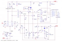
The gain of this circuit is going to be pretty low. The power tubes and OPT combined have a gain of about unity, so all of the loop gain has to come from the first stage. The 12AX7 will have a gain of about 50 in this config, so with a closed-loop gain of 10, you have a feedback factor of about 5. I guess that's not too bad. I think the Williamson used a 10x feedback factor at high frequencies, and more like 50x at middle and low frequencies.
I'd also be concerned that those 220k resistors won't provide enough base current to the emitter followers. Or at least, the base current will drop enough voltage across them that the power tube bias will vary as the transistor beta changes with temperature, so the bias will end up less consistent than if you had used MOSFETs.
Have you seen Morgan Jones' Crystal Palace design? If you added an extra stage to your circuit, it would end up quite similar to that.
Last edited:
I am very skeptical about your output power needs. It could be the case that you need that much, but very highly likely that you don't. But again, the only way to find that out would be to make some small experiments.
Same thing with NFB. You will never be able to know how you feel about the sonic impact of NFB unless you make some experiments and try things out.
You know my line of thought; I've personally found that maximizing tube linearity without NFB yields supremely best results. Why allow distortion and then remove it with NFB? Best not to make it in the first place.
You would know so much more with just a couple of experimental breadboard circuits than with years of thinking about NFB and output power.
What do you mean by using no global NFB to lower output impedance? Also to NFB, I have no idea whether it is good or bad. I just read a lot of post here.
I read a lot of comments suggesting not to use global NFB. Maybe this is wrong, I don't know. I just did this draft design based on my understanding of what people said here.
A lot of the SE design has no GNFB, don't they see the same problem as you described? Then how come people keep doing that?
Some use a single full range driver on a baffle (like Fostex), which has a milder impedance curve. Some use Magnepans for example, which can be mostly resistive.
Please don't think everyone here is an expert, and even experts disagree strongly on lots of things. You'll hear lots of contradictory opinions that may not be relevant to you,
so come to your own conclusions and don't build an amplifier designed by a committee.
Last edited:
I just want to throw this out. I modified the design to have global NFB, but this one has low loop gain. Please comment.
Usually the 0 Ohm tap is grounded and the nfb taken off either the speaker's tap or the 16 Ohm tap. As is, this won't work.
Hi all:
Thanks for the advice. I made a mistake in the NFB, I corrected it with 0ohm tap to ground and FB from 4 ohm tap. Also, I am convinced N MOSFET is the way to go for the follower, so I changed that also.
As I said before, I am very green in audiophile amp requirements, anyone of you have more experience than me in what improve that sound. That's why your comments are so important to me as this is more important than making the circuit perform as designed. This schematic is more like a draft so you guys can comment on and I'll try my best to understand and filter out to what I want.
One thing I also want to explain, I do have experience in analog design and successfully designed/built a few guitar amps with power amp part that have adjustable power output, those are as or more complicate than this one. I had a lot of experience in CCS design like in the circuit because I have years of experience in designing analog IC that used nothing but CCS. So this design is not aggressive at all by any stretch. So don't worry about me taking too big a bite and need to start small and build up to a more advanced circuit.
I understand that chances I have to modify and compare, but I don't want to start with very basic design or a known basic design and plan to build the second and third one. This circuit is just a basic power amp found in typical guitar amp if I remove the two source follower and the CCS!!! I already built a few of the basic power amps already.
My plan is to use my 100W Fender Bassman as the test bed because it has a 100W power amp PT already. That should be good enough to power two channels. I can use that to experiment and to improve that design before I build the real one. As of now, my plan is to buy the Lundahl 1679 OPT. Then I can compare triode vs UL.
Thanks
Attachments

Last edited:
If you are building this amp specifically for your speakers then my approach would be to find out as much about them as possible, whether this is through the power of your google-fu or doing some technical analysis yourself. Maybe draw up a simple frequency plot for your speakers and see what it looks like. There is a lot of info for speakers that are quite useful, knowing if the Q is already high or low will help to know how much control or lack there of on the drivers you will need in an amp.
If you are building this amp specifically for your speakers then my approach would be to find out as much about them as possible, whether this is through the power of your google-fu or doing some technical analysis yourself. Maybe draw up a simple frequency plot for your speakers and see what it looks like. There is a lot of info for speakers that are quite useful, knowing if the Q is already high or low will help to know how much control or lack there of on the drivers you will need in an amp.
I already gone through Google before, there is no technical information at all. Ha ha, a lot of the post are not in English!!!!
What is the easiest way to characterizing the speaker? Use a generator? I only have one with 50ohm output. Do I just drive it and plot out the amplitude and phase from 20Hz to 20KHz?
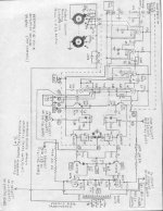
A couple of years ago I built a 6L6 amp that had two stage 6SN7 LTP, DC coupling between the LTPs, MOSFET source followers and DC balance adjust. The thread of the build is here http://www.diyaudio.com/forums/tubes-valves/133034-6l6gc-ab2-amp.html
The final schematic was the .pdf in the link below. The VR tubes were just for giggles. Sand would do a better job, but not look as impressive 😉
You may find some of the ideas useful.
Cheers,
Chris
The final schematic was the .pdf in the link below. The VR tubes were just for giggles. Sand would do a better job, but not look as impressive 😉
You may find some of the ideas useful.
Cheers,
Chris
Attachments
What is the easiest way to characterizing the speaker? Use a generator? I only have one with 50ohm output.
Do I just drive it and plot out the amplitude and phase from 20Hz to 20KHz?
You can simply drive the speaker with your signal generator through a 1k resistor. This will give you a pretty good idea of the impedance curve,
just a little off on the peaks. Of course, you can use a power amplifier and a larger resistor, for better accuracy. The idea is to drive it with a
reasonably good constant current source, so the voltage across the speaker is proportional to the impedance.
Last edited:
The easiest way to measure your speaker's impedance curve is to get one of the WT ("woofer tester") or DATS devices. Gets you impedance mag (ohms) and phase very quickly. You could load that data as a "ZMA" file into Xsim and try different networks across the speaker terminals (never in series) to bring the curve down to a relatively constant impedance over the speaker's range
- Status
- Not open for further replies.
- Home
- Amplifiers
- Tubes / Valves
- Why some people want DC coupling in power amp?