instead of bjt's i will use a mosfet instead, bjt's load the preceding tubes more than a mosfet will...voltage gain is low because of this...
probably the reason why not many are doing this...
probably the reason why not many are doing this...
I the reason is Vbe is smaller and more consistent. I don't use GNFB, gain is not an issue. I am even thinking about putting cathode degenerate resistor in the LTP to stabilize and lower the gain.instead of bjt's i will use a mosfet instead, bjt's load the preceding tubes more than a mosfet will...voltage gain is low because of this...
probably the reason why not many are doing this...
For me main reason is less capacitor in circuit path.
But design gets much harder...
I don't like the zener diode in my design. I don't like the noise and more drift. It is just much more tedious to do DC coupling with PP. It is much more simple for SE as you only have half to worry about and no balance to worry about. Drifting out of balance in the power tubes will be a real killer as you start having DC imbalance in the OPT and that really hurts.
I put the DC blocking cap between the LTP and the emitter follower because there will be no sudden surge of current like the grid current of the triode. In fact, I intentionally use CCS for the emitter follower so the current don't change. So the base current is constant regardless of the swing.
I the reason is Vbe is smaller and more consistent. I don't use GNFB, gain is not an issue. I am even thinking about putting cathode degenerate resistor in the LTP to stabilize and lower the gain.
in the case of the bjt's the input impedance of the emitter followers are in parallel with the plate load resistors...that is why the voltage gain is low...
mosfets do not need input currents....
why not use an IC instead to drive the emitter followers?😉
Actually I am thinking about using 6SN7 that has low gain and low ra that pretty much swamp the plate load resistor and the input resistance of the BJT. I am still open to use MOSFET source follower, I just need to research the drift of Vgs with temp. To me, the biggest concern is imbalance of the two power tubes that result in net DC current through the OPT. That's the reason I choose BJT as the Vbe only drift by mV.in the case of the bjt's the input impedance of the emitter followers are in parallel with the plate load resistors...that is why the voltage gain is low...
mosfets do not need input currents....
why not use an IC instead to drive the emitter followers?😉
Regarding to using IC as the differential stage, then we get to why not do it in SS all together. the reason I use emitter follower is because it is as transparent as it can be because it does not add any distortion. All the transistors I used in the circuit are either emitter follower that does not add anything or CCS that just provide high impedance current sink. The tube is still doing 100% of the job.
if current imbalance in the output tube is your main concern, then why not use a separate ccs for each output tube, this way you are assured of perfect balance...
Because I am doing differential power tubes aka Vacuum State amplifier. Also, if you do separate current source, you have to have big bypass cap for the cathode. Then you introduce a worst problem with a big electrolytic capacitor. That defeats all the work to eliminate signal caps. This will be much worst.if current imbalance in the output tube is your main concern, then why not use a separate ccs for each output tube, this way you are assured of perfect balance...
you can still try it without those caps..
is this your first build or have you built other tube amps before?
there are a lot more other things to consider in designing tube amps.
first is gain sensitivity, what is your goal? how many volts of input
do you need to get the desired power output...
knowing this, lets you decide how many stages you need to achieve this goal.
topology then comes next...
if your aim is bandwidth, what is it? and how many watts?
bandwidth at 1 watt level is not the same as bandwith at say 50 watts,
a lot of other factors are at play here...
Miles Prower did a nice and informative design walk-thru, i hope he chimes in,
he posted it here years ago, i just can not recall right now...
I designed and build a few tube guitar amps with power scaling, channel switching. I am not that familiar with tubes, but I think I am experience in general electronics.you can still try it without those caps..
is this your first build or have you built other tube amps before?
Without the cap at the cathode, you have no gain!!!! You won't have any signal to the OPT. This is a simple common cathode stage we are talking about. You remove the cap, you totally loss the common cathode part of it as the CCS is high impedance.
Last edited:
As I said, this is a common cathode stage, if you use CCS tail without cap bypassing, it is like with very high cathode resistor. You loss all the gain.not too sure about that....
The only way to get away from this is like what I drew, differential power stage where the cathode of each power tube sees the impedance of the cathode of the other power tube. This become a LTP with gain. then you can use CCS tail without the need of a bypass cap at the cathode. I did give a lot of thought on this.
Not to mention one even more important thing. You increase the impedance at the cathode, you increase the output impedance at the plate. This will increase the output impedance at the output of the OPT to the speaker. Part of using triode or UL is to lower the output impedance of the output to better drive the speaker's reactive load. I already thought about adding cathode degenerating resistor for the power tube and I decided against it because that increase the output resistance of the amp.
Last edited:
you are probably right, what i do in my builds is use cathode resistor/capacitor biasing....
listening test shows that participants can not tell it apart from a fixed bias amp..
listening test shows that participants can not tell it apart from a fixed bias amp..
I stuck a shunt regulator in the cathode of the 833 to provide cathode bias voltage. What's cool is it also sinks all the 833 current right through the pass MOSFET of the regulator to ground (40W dissipation at idle). It acts as a bypassed resistor, without a bypass cap. I use an IRFP450 TO-247 MOSFET.
I stuck a shunt regulator in the cathode of the 833 to provide cathode bias voltage. What's cool is it also sinks all the 833 current right through the pass MOSFET of the regulator to ground (40W dissipation at idle). It acts as a bypassed resistor, without a bypass cap. I use an IRFP450 TO-247 MOSFET.
Shunt regulator is a voltage source with low impedance. Then you go right back to grid bias that has voltage drift.
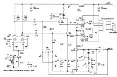
Here is the more detail drawing of my design. The two AC coupling cap is C2 and C25 between the LTP and the emitter followers. I raise the grid of the power tube to +80V to get only 300V across the power tube to lower power dissipation. Using differential output tube let me get away without the cathode cap. With the CCS tail for the power tubes, the absolute grid voltage becomes non important. Only the TPOT2 needed to be adjust the balance to zero out the DC current in the OPT.
There is no global NFB, so I use 6SN7 with 1K emitter degenerate resistor to keep the gain below 20. The gain from the power tubes to the speaker is less than one, so the gain of this power amp should be about 20. I might change to a 12AX7 and do a global NFB. But the low loop gain make the NFB not very effective and hopefully not making it sounds like a SS amp.
The emitter follow will not have a sudden on set of base current like the grid of a triode, so there will not be a charging up and blocking problem like tubes. Vbe of the emitter follower is very stabe ( only -2mV/deg C) and with CCS tail, they will not have any distortion contribute to the whole circuit.
Please comment on this design.
Thanks
Attachments
Last edited:
Can you explain?ever wondered why not many had that design? build it and you shall soon find out...
No I don't, I just design according to what people talking here.
1) LTP with CCS.( ala Morgan Jones)
2) DC couple low impedance driver of power tubes.( according to Jones and people here about blocking problem)
3) UL for lower output impedance.
4) No NFB to get more natural sound.
5) Concept of differential power tubes from very expensive Vacuum State that has good review.
Last edited:
Can you explain?
no...that is for you to find out...😉
my unsolicited advice....
build an amp based on conventional designs,
then build you own design and then compare,
then come back to us and tell us what you learned...
Can anyone comment on my circuit. I am still very green regarding to the sound. I know the circuit will work electrically, but I have no idea how it will sound.
I don't care whether this is like any successful design or not. I want to know if there is anything in the circuit that I should not do, that people think it's not going to produce good sound. I don't plan to build many amps, I am hoping to learn what is good and what to avoid and build a good one the first time. I based on comments here to pick and choose the design and hope to get the best and come up with this.
Thanks
Shunt regulator is a voltage source with low impedance. Then you go right back to grid bias that has voltage drift.
Funny, my idle current doesn't drift. At all.
- Status
- Not open for further replies.
- Home
- Amplifiers
- Tubes / Valves
- Why some people want DC coupling in power amp?