REW (and others also, I guess) do not open the 32-bit float wav (only signed supported), so expanding to 64 bits seems pointless anyway ?It looks like wavwrite() has been replaced by audiowrite(), which can handle doubles. https://www.mathworks.com/help/matlab/ref/audiowrite.html
See post #356I've been attempting to implement this using jriver's PEQ blocks alone (using my app which can calculate how to use it to create bessel filters already - https://yabb.jriver.com/interact/index.php/topic,129609.0.html). I was failing to achieve the expected HPF slope for a while until I eventually realised that the missing link was mentioned in this post
I may have missed it but is there a method available to calculate the required scaling factor for different filter orders?
The 8th order scaling was calculated from gberchin's scaling, the fourth order emperically but is to within a fraction of 1Hz @100Hz.

I'm not convinced. I still have the opinion that if one implement a crossover which is:
Then any FR or phase anomaly can be afterwords corrected to perfection by using global FIR on the speaker. I.e. there is not performance advantage to substitute the above IIR mechanism for FIR.
//
- adequately steep to prevent distortion (IIR)
- forms the intended slope acoustically (IIR), which most often require that...
- driver is FR linear in its stop band before XO is applied (IIR)
Then any FR or phase anomaly can be afterwords corrected to perfection by using global FIR on the speaker. I.e. there is not performance advantage to substitute the above IIR mechanism for FIR.
//
Except the FIR approach will introduce more delay and will ring if not acoustically summed accurately (which they won't fully unless drivers are within 1/4 wavelength and with the same dispersion properties) unlike the GB filters.I'm not convinced. I still have the opinion that if one implement a crossover which is:
- adequately steep to prevent distortion (IIR)
- forms the intended slope acoustically (IIR), which most often require that...
- driver is FR linear in its stop band before XO is applied (IIR)
Then any FR or phase anomaly can be afterwords corrected to perfection by using global FIR on the speaker. I.e. there is not performance advantage to substitute the above IIR mechanism for FIR.
//
Hi all,Yes, exactly the point. 👍
When it comes to real-time filtering, IIR is king.
That was my inclination before this thread.
But I'm now inclined to believe that both IIR or FIR end up with the same constant delay for the same realized xover topology.
This thread, and the delay needed by the MDS method @gberchin provided, have reinforced that belief.
Hey Greg, if all phase rotation were removed from a given IIR xover topology by a series of IIR all-pass filters, would this too give the same constant delay as lin-phase? (seems like is has to as well)
(By same xover topology, I mean same xover freq, high-pass order, low-pass order, and combined mag and phase traces.)
So i think it just comes down to computational resources and implementation tools available. (assuming IIR is also via DSP)
I think the biggest problem is the driver needs to be FR linear in its entire summation band (not just its stop band, but maybe summation is what you meant).I'm not convinced. I still have the opinion that if one implement a crossover which is:
- adequately steep to prevent distortion (IIR)
- forms the intended slope acoustically (IIR), which most often require that...
- driver is FR linear in its stop band before XO is applied (IIR)
Then any FR or phase anomaly can be afterwords corrected to perfection by using global FIR on the speaker. I.e. there is not performance advantage to substitute the above IIR mechanism for FIR.
//
I typically consider the the summation band to extend down to -30dB.
That said, If some very well tuned speaker, done with min-phase driver by driver EQs, and then by adding IIR xovers.........
then and only then, do i think globally phase linearizing just the IIR overs, works as well as using lin-phase xovers.
If however, global FIR of mag and phase is applied to the acoustic measurement of the entire speaker, it's going to be too specific to the measurement location, ime.
Only mag variations that are not summed responses, ie where one driver is the sole contributor, are globally correctable. .....(and these corrections are optimally already done at the driver level.
Only phase variations from linear, produced by xover rotations are globally correctable.
So any regions of non-summation should already have been optimized, and any regions of summation should have nothing bt their phase rotations corrected.
Spatial measurement averaging helps reduce overcorrection to a spot, but not nearly as much as spatial averaging at the driver-by-driver level, prior to adding xovers.
Hope that all made sense....my 2c.
Except the FIR approach will introduce more delay and will ring if not acoustically summed accurately (which they won't fully unless drivers are within 1/4 wavelength and with the same dispersion properties) unlike the GB filters.
That's what I've been thinking too about ringing.
But something in me keeps saying all processing roads have to lead to equivalence, when a given amount of phase rotation is linearized. So I wonder if the MDS method also has the same theoretical propensity for pre-ring as linear phase.
It must be understood that IIR and FIR refer only refer to implementations, not to the underlying mathematics. Those mathematics are inviolate -- an impulse response that is left/right symmetric has linear phase, and vice versa. (Well, there are some pathological exceptions, but they involve infinities and are thus really difficult to implement.) We can implement a symmetric impulse response exactly, via a FIR filter, or approximately, via an IIR filter. A linear-phase FIR filter must incorporate delay equal to half its length, in order to be causal. An IIR filter will automatically create whatever delay it needs to be causal.Hey Greg, if all phase rotation were removed from a given IIR xover topology by a series of IIR all-pass filters, would this too give the same constant delay as lin-phase? (seems like is has to as well)
The reason that an IIR filter might not exhibit as much delay as an (approximately) equivalent FIR filter is that the IIR filter "cheats" -- it is not truly linear-phase at all frequencies. If we design that IIR filter correctly, then the nonlinear phase will occur outside the passband, where we don't really care about it all that much. If we add further processing that exactly linearizes the phase of that IIR filter at all frequencies, then the delay will be the same as or greater than that of the equivalent FIR filter. @mark100, I hope that answers your question.
Last edited:
Sorry, I didn't notice this statement until after I had responded, above.So I wonder if the MDS method also has the same theoretical propensity for pre-ring as linear phase.
The answer is yes. If you create a lowpass filter with significant pre-ring, then the MDS highpass will exhibit the same pre-ring, out-of-phase with that of the lowpass section. The only reason that the Gaussian MDS crossovers don't exhibit significant pre-ring is that the Gaussian lowpass filter itself has the least amount of pre- and post-ring of any filter, for a given bandwidth. So it's not the MDS structure that makes these crossovers attractive; it's the Gaussian LPF (or its Bessel approximation).
Thank you very much. I've puzzled these things for a number of years.Sorry, I didn't notice this statement until after I had responded, above.
The answer is yes. If you create a lowpass filter with significant pre-ring, then the MDS highpass will exhibit the same pre-ring, out-of-phase with that of the lowpass section. The only reason that the Gaussian MDS crossovers don't exhibit significant pre-ring is that the Gaussian lowpass filter itself has the least amount of pre- and post-ring of any filter, for a given bandwidth. So it's not the MDS structure that makes these crossovers attractive; it's the Gaussian LPF (or its Bessel approximation).
And i totally get the "cheat" aspect.....how the MDS relaxes true linear-phase.
I think that kind of cheat is kin to what I've learned to do empirically with a constant size FIR filter, as I move impulse centering more towards the start to reduce delay (and beneficially gain frequency resolution).
Dear Mark,Hey Greg, if all phase rotation were removed from a given IIR xover topology by a series of IIR all-pass filters, would this too give the same constant delay as lin-phase?
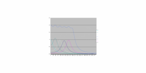
The reason for your above concern is simply that you believe all-pass filters to "remove phase rotation", but the truth is that they're there to add the same. The total delay depends on how much is added, and as you might have already noticed from previous examples, the minimum final delay that can be achieved is equal to the passband group delay of the initial IIR filter. The picture below says better.
It is fairly easy to see how the IIR (Bessel) and linear phase (FIR) have more or less same phase upto 200Hz where the response is already down by several dB. The job of the IIR all-pass would be to add (not remove) enough phase to the blue (IIR) so that its phase equals that of the red (linear phase). This difference is shown in grey.
Note that the IIR above is a Bessel filter. This was chosen for illustration purposes.
Hope that helps.
To be precise, it's not the MDS structure that relaxes true linear phase; it's the Bessel lowpass filter. MDS only guarantees "perfect reconstruction", which means that the lowpass and highpass outputs sum perfectly to the input waveform, whether or not the lowpass filter portion is linear-phase.And i totally get the "cheat" aspect.....how the MDS relaxes true linear-phase.
Thanks 🙂Dear Mark,
The reason for your above concern is simply that you believe all-pass filters to "remove phase rotation", but the truth is that they're there to add the same. The total delay depends on how much is added, and as you might have already noticed from previous examples, the minimum final delay that can be achieved is equal to the passband group delay of the initial IIR filter. The picture below says better.
View attachment 1131509
It is fairly easy to see how the IIR (Bessel) and linear phase (FIR) have more or less same phase upto 200Hz where the response is already down by several dB. The job of the IIR all-pass would be to add (not remove) enough phase to the blue (IIR) so that its phase equals that of the red (linear phase). This difference is shown in grey.
Note that the IIR above is a Bessel filter. This was chosen for illustration purposes.
Hope that helps.
I'm on board and familiar with what you showed.
Have you ever seen the technique where a whole slew of all-pass filters are used in series to basically add phase incrementally all the way out the curve such that phase is added to be level with phase at the starting (low end) of the curve?
Arduous and impractical.....but I've seen it done a few times.
Adding phase in increasing amounts as frequency increases, it translates into first partial, then full, then multiples cycles of frequency response rotation.....iow, frequency dependent delays. Which ultimately creates flat phase becomes by the the VHF end finally matching phase, with the starting low freq end.
That's the the technique. That i intuit (rightly or wrongly) will have to match whatever delay it takes to achieve linear-phase via FIR or whatever.
Back to the idea it takes time to fix time.
And is why delay is not really a matter of IIR vs FIR.... (IIR can be made to have delay, witness MDS. And FIR is often used with no delay)
Imo, it's just a matter of how flat do you want phase given a chosen xover topology/order....
and are you willing to pay the price of the delay needed to get it.
Unfortunately, that will not result in a linear phase system. All pass filters are nonlinear phase and as such introduce constant delay at low frequency with the delay becoming smaller as frequency increases. The result is the low frequency group delay increases with each additional stage of all pass but there is no increase in GD at high frequencies. At best, you can add a constant delay over a prescribed frequency range from DC to some upper limit, but that just amounts to adding excess phase to the minimum phase response of the original filter over that frequency range and as no effect on phase linearzation.d.
Have you ever seen the technique where a whole slew of all-pass filters are used in series to basically add phase incrementally all the way out the curve such that phase is added to be level with phase at the starting (low end) of the curve?
Arduous and impractical.....but I've seen it done a few times.
Adding phase in increasing amounts as frequency increases, it translates into first partial, then full, then multiples cycles of frequency response rotation.....iow, frequency dependent delays. Which ultimately creates flat phase becomes by the the VHF end finally matching phase, with the starting low freq end.
That's the the technique. That i intuit (rightly or wrongly) will have to match whatever delay it takes to achieve linear-phase via FIR or whatever.
Phase linearization, no matter whether done with IIR on FIR, is not about adding delay but passing the signal through a filter that has the inverse of the minimum phase filter which is to be linearized.
A judiciously designed allpass filter can, in many cases, alter the phase response of a nonlinear-phase filter to approximate linear phase "from DC to some upper limit". As that upper limit increases, so must the order of the allpass filter, since only 180° of phase shift per filter order is available. At high frequencies and large delays, the order can become untenably large.At best, you can add a constant delay over a prescribed frequency range from DC to some upper limit, but that just amounts to adding excess phase to the minimum phase response of the original filter over that frequency range and as no effect on phase linearzation.
Are you referring to forward/backward filtering? If so, that results in a zero-phase transfer function, which still has to be delayed for causality. That was discussed in some of the early posts in this thread.Phase linearization, no matter whether done with IIR on FIR, is not about adding delay but passing the signal through a filter that has the inverse of the minimum phase filter which is to be linearized.
Otherwise, I do not understand what you mean by "a filter that has the inverse of the minimum phase filter which is to be linearized". If that filter alters only the phase response, and not the magnitude response, then it is an allpass filter. Causal allpass filters can only introduce positive group delay: http://sepwww.stanford.edu/sep/prof/pvi/spec/paper_html/node22.html
You may wrap the phase around to call 360* (and its multiples) zero degrees all day, but the time delay introduced will not be negated by adding all-pass stages. It's a bit like how the sum of two positive numbers cannot be less than the numbers themselves.I'm on board and familiar with what you showed.
Adding phase in increasing amounts as frequency increases, it translates into first partial, then full, then multiples cycles of frequency response rotation.....iow, frequency dependent delays. Which ultimately creates flat phase becomes by the the VHF end finally matching phase, with the starting low freq end.
That's the the technique.
If the phase turning is truly undone (removed), then the related delay would also be undone, which doesn't happen here. If it were like you say, then fourth order filters would be the same delay as first order filters, as every 360* would be the same as zero degrees !
You're not fixing it, you're just adding loads more of it to make it appear more constant.Back to the idea it takes time to fix time.
Basically, yes, but there's still a limit to that, which is what I showed above. No linearised filter (based on FIR or IIR) can have a delay less than the group delay of the original IIR filter. Also, what is flat is the delay, not the phase. Phase is linear.Imo, it's just a matter of how flat do you want phase given a chosen xover topology/order....
and are you willing to pay the price of the delay needed to get it.
Yes, true undoing of phase could be done only byAre you referring to forward/backward filtering? If so, that results in a zero-phase transfer function, which still has to be delayed for causality. That was discussed in some of the early posts in this thread.
- Turning the filter around (FIR)
- Turning the signal around (IIR, approximate)
- Turning time around (IIR / FIR, but theoretical only)
Maybe what was meant was an FIR correction filter with a larger positive delay for causality.Otherwise, I do not understand what you mean by "a filter that has the inverse of the minimum phase filter which is to be linearized".
REW has been able to import and save 32 bit float files for quite a while now.REW (and others also, I guess) do not open the 32-bit float wav (only signed supported), so expanding to 64 bits seems pointless anyway ?
The filter does not only have to be in one part, you can convolve multiple corrections together. You could create an analytically derived phase correction just for the known crossover topology and use that in conjunction with an overall filter based on a measurement.If however, global FIR of mag and phase is applied to the acoustic measurement of the entire speaker, it's going to be too specific to the measurement location, ime.
In a room the best sound will be position dependent, there is no getting away from that, even with multiple subwoofers and other techniques, there will still be some volume of space where the sound is better than it is elsewhere. That can be small or large but it cannot be everywhere.
Start working on the bass in a defined location with both in room magnitude and phase and I think you will find some worthwhile improvements.
That description may not sound very scientific or technical but it hits the nail on the head.Back to the idea it takes time to fix time.
Enclosed you will find a graph of how GD EQing works by using 2nd order allpass sections. The cyan one is the GD response of the crossover itself. The dark blue one is the summed group delay of the crossover and the cascaded 2nd order allpass sections. The other curves show the GD of each of the allpass sections alone. The number of allpass sections needed rises with the bandwith over which the GD has to be linearised, the "DC GD" of the crossover and the desired linearity of the corrected GD.
There is no closed-form solution to design such an equaliser, it has to be done by approximation.
Regards
Charles
Attachments
I have made this work on a 2 way box with LR24's @ 2KHz a few years ago, easiest to start unwrapping from the highest frequencies and work down. I think Meyer Sound were doing this in the 1980's with their UPA's etc.That description may not sound very scientific or technical but it hits the nail on the head.
Enclosed you will find a graph of how GD EQing works by using 2nd order allpass sections. The cyan one is the GD response of the crossover itself. The dark blue one is the summed group delay of the crossover and the cascaded 2nd order allpass sections. The other curves show the GD of each of the allpass sections alone. The number of allpass sections needed rises with the bandwith over which the GD has to be linearised, the "DC GD" of the crossover and the desired linearity of the corrected GD.
There is no closed-form solution to design such an equaliser, it has to be done by approximation.
Regards
Charles
Yes, and the PSI studio monitors do it still that way nowadays. They do it also with their three way models which needs quite an effort.Meyer Sound were doing this in the 1980's with their UPA's etc.
Regards
Charles
Hi Gregory. Been a long time. Correct me if I'm wrong, but I don't see this. Explain to me now. I would agree that an FR filter could be constructed that had non linear phase such that the delay increased with frequency such that the sum of the LP phase and the band pass phase would be that of a constant delay. But just adding stages of typical band pass filters won't linearize nonlinear phase of an LP filter. Here is a figure of an LR2 LP at 1lk and an all pass filter with F0 at 2k Hz plotted on a linear scale. In both cases the phase starts out linear but ultimately the phase is concave upward meaning the delay decreases with frequency. Adding a series all pass such as this would increase the delay at low frequency but at higher frequencies again the added delay becomes less and less with increasing frequency. To extend the region of linear phase, or constant delay, would require that the all pass would have a phase response what was concave downward. How would you achieve that w/o and FIR type filter?A judiciously designed allpass filter can, in many cases, alter the phase response of a nonlinear-phase filter to approximate linear phase "from DC to some upper limit". As that upper limit increases, so must the order of the allpass filter, since only 180° of phase shift per filter order is available. At high frequencies and large delays, the order can become untenably large.
Are you referring to forward/backward filtering? If so, that results in a zero-phase transfer function, which still has to be delayed for causality. That was discussed in some of the early posts in this thread.
Yes, for IIR implementation. And yes, a delay has to be added for causality so it can be processed int he real world. Agreed.
Otherwise, I do not understand what you mean by "a filter that has the inverse of the minimum phase filter which is to be linearized". If that filter alters only the phase response, and not the magnitude response, then it is an allpass filter. Causal allpass filters can only introduce positive group delay:
Well, this is semantics. An FIR filter can be constructed with phase as pictured below, in theory, which when in series with the LR2 pictured above would result yield a zero phase (zero delay) response. Such a filter has less "negative delay" as the frequency increases. But this filter has negative GD (delay) and as you point out would be non causal. Thus, to process the filter, i.e. make it causal, a constant delay, Td, (shift of the impulse to the right) is required. Thus, the resulting filter has increasing delay as F increases. The result is then a linear phase response with phase = Td x F.
That's the point I'm trying to get across. Going back the the figure in post 429, the only way to get added phase at high frequency while not adding any at low frequency is to have a delay which increases as F increases. No typical analog, passive or active, or IIR filter will have that property because such a filter must be non causal. What is necessary is to take the non causal filter, as I described above, and make it causal by adding a sufficient constant delay, shifting the impulse to the right.
Let me put this another way. Let the phase of the LP filter be some nonlinear function G(f). Now, let the all pass filter have phase H(f). The phase of the LP filter in series with some number of all pass filters is G(f) x H1(f) x H2(f) x...x Hn(f) where n is the number of all pass filters. Now, even is the all pass filters were linear phase there is no reduction of the nonlinearity of the phase of G(f).
Last edited:
Hi JohnTo extend the region of linear phase, or constant delay, would require that the all pass would have a phase response what was concave downward.
You need to use 2nd order allpass filters that have a faster turning/dropping phase response around their pole frequency. This means that they have a peaking group delay response. You can see in the graph that I posted above how it works. It does always work over a limited bandwidth only. For large bandwidths a large number of allpass filters is needed. Above the useful range gropup-delay drops like a stone and the step response does also show some out of band pre-ringing.
This type of EQ does nothing else than generating additional group-delay where the unequalised crossover has less of it originally.
Regards
Charles
- Home
- Loudspeakers
- Multi-Way
- Why not IIR filters + a global phase linearization by FIR