Question came up in another thread....thought it best to reply in a new thread....
A big reason that I think NOT to use global FIR on top an existing speaker setup, be it passive or active,
is to avoid pre-ring.
Out-right pre-ring is obvious in electrical IIR xovers summed together and then phase-linearized globally in a subsequent processing stage .
Here are two Linkwitz-Riley 24dB/oct IIR xovers at 200Hz and 1300Hz that are summed together to give mag and phase traces as shown, and are as expected.
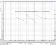
Here is after global phase correction is applied, and is as expected. (slight phase drift at 20kHz...not being picky here for this simple demo)
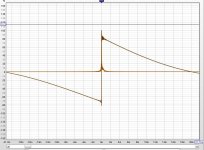
Here's the step response to look at. Out-right pre-ring is not pretty.
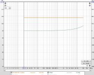
Ok, the same two Linkwitz-Riley 24dB/oct xovers at 200Hz and 1300Hz are summed together, but now are linear phase.
Flat mag and phase as expected.
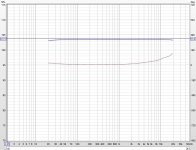
With an essentially a step response free of pre-ring.
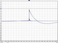
Ok, i hope that makes a pretty good case against global FIR phase correction. There's more reasons to avoid global, but that's the easiest one to show some quick meas.
A big reason that I think NOT to use global FIR on top an existing speaker setup, be it passive or active,
is to avoid pre-ring.
Out-right pre-ring is obvious in electrical IIR xovers summed together and then phase-linearized globally in a subsequent processing stage .
Here are two Linkwitz-Riley 24dB/oct IIR xovers at 200Hz and 1300Hz that are summed together to give mag and phase traces as shown, and are as expected.

Here is after global phase correction is applied, and is as expected. (slight phase drift at 20kHz...not being picky here for this simple demo)

Here's the step response to look at. Out-right pre-ring is not pretty.

Ok, the same two Linkwitz-Riley 24dB/oct xovers at 200Hz and 1300Hz are summed together, but now are linear phase.
Flat mag and phase as expected.

With an essentially a step response free of pre-ring.

Ok, i hope that makes a pretty good case against global FIR phase correction. There's more reasons to avoid global, but that's the easiest one to show some quick meas.
Anyone not in favour of FIRs may carry out some (not bad) phase linearisation using higher order IIR all-pass filters, however with an increased overall delay that is similar to that of FIR filtering.
@mark100 , something must have gone wrong in your sims.
Complex Transfer functions simply multiply, distributive law at work.
Let TF1(s) and TF2(s) be you minphase IIR LR filters, and AP(s) the FIR correction kernel -- which is the time inverse of the summed impulse response having the exact inverse phase characteristic of your filters (both of them, as they are LR and thus 0deg phase offset).
[TF1(s) + TF2(s)] * AP(s) = TF1(s)*AP(s) + TF2(s)*AP(s).
Global phase unwrapping with an analytically derived "clean" phase inversion FIR kernel is the best way to do it IME and IMHO. Phase unwrapping this way does not create any additional artifacts. And is is computationally very efficient. Grimm Loudspeakers (of Bruno Putzeys) have a paper on the topic: https://www.grimmaudio.com/wordpress/wp-content/uploads/speakers.pdf (see section 2.3).
Obviously, the basis for that should be a clean minphase design which means XO's with tightly matched zero phase offset between ways down to -30dB.
Obviously, the basis for that should be a clean minphase design which means XO's with tightly matched zero phase offset between ways down to -30dB.
Mark100, try reversing an output sequence and feeding it through the same filter and then reversing the (now) obtained output once again to cancel the phase turned by the filter.
Zero-phase filtering
Zero-phase filtering
Can't say I understand your specific examples Mark, nor do I agree with your conclusion. If I do a quick LR 24 crossover at 1300 and 200, like you, and compensate for it using a RePhase generated compensation, while leaving magnitude flat from 20 Hz until 20 KHz, I get a STEP response like expected, flying high to resemble its bandwidth:

I would not know of any reason to expect otherwise. I can't explain your triangle shaped STEP if magnitude is flat from 20 Hz up to 20 KHz.
I'd say something must have gone wrong on your side. I didn't take the time to make the alignment perfect, but I guess this already shows one can perfectly compensate these crossovers as long as they behave like textbook examples. Doesn't matter if one uses linear phase or linerize it after the fact, the end result should be the same or something went terribly wrong.
Magnitude and phase of the LR sum:

Rephase generated phase compensation for both crossovers:

I would not know of any reason to expect otherwise. I can't explain your triangle shaped STEP if magnitude is flat from 20 Hz up to 20 KHz.
I'd say something must have gone wrong on your side. I didn't take the time to make the alignment perfect, but I guess this already shows one can perfectly compensate these crossovers as long as they behave like textbook examples. Doesn't matter if one uses linear phase or linerize it after the fact, the end result should be the same or something went terribly wrong.
Magnitude and phase of the LR sum:
Rephase generated phase compensation for both crossovers:
Last edited:
To demonstrate what it would look like if I sum the tweeter, mid and woofer using linear phase crossovers:

Done exactly the same way, but this time I generated the filtered files with linear phase crossovers within RePhase.
As expected, the results look exactly alike. See attached REW file with all the samples as shown here...
I have to say aligning the linear phase crossovers is way simpler than aligning the LR24 filters, but if done secure, the end result should always be exactly the same between both methods. If it isn't, something must be wrong. It should not make any difference in pre-ringing.
Attachments
Last edited:
I'm not sure what I'm looking at in the various graphics above, but if pre-ring is what you are trying to eliminate, then linear phase is exactly the opposite of what you want to implement. There are some fundamental mathematics at work here, specifically:
A linear-phase (and zero-phase is a form of linear phase) frequency response always results in a symmetric impulse response, and vice-versa.
In other words, the impulse response before the peak will always be the mirror image of the impulse response after the peak. (It may also have its polarity inverted.) If you want to minimize the activity prior to the impulse response peak, then minimum-phase is the way to go -- minimum phase concentrates the energy as close to the beginning of the impulse response as possible.
More math:
A Gaussian-shaped, linear-phase frequency response also results in a Gaussian-shaped impulse response.
Any other shape will result in ringing in either the time domain or the frequency domain (as ripples in the response) or both. You can design an impulse response that does not ring, in which case the frequency response will have ripples. You can design a frequency response that has no ripples, in which case the impulse response will ring.
Last bit of math:
If a perfect-reconstruction crossover is implemented, then ringing in one band will be accompanied by identical ringing of opposite polarity in the other band.
The ringing will still occur, but the highpass ringing will cancel the lowpass ringing perfectly. Unfortunately, what cancels mathematically won't necessarily cancel acoustically.
Hi all, thank you for the replies, offers to help, and instructional comments.
let me make a series of a few quick individual replies, and then I'll lay out in better detail what I did /am doing...
@Alex, hope I'm not leading you and others on a goose chase...i don't think so, but we'll see....
@charlie, yep, always the chance i did something wrong. price of self-eductation i guess. Thx for your willingness to look at what i've done. Btw, congrats on your PE win.
@KSTR, i can kinda follow your math, but not so fully that I feel i understand it gut level. I do get the idea of complex transfer multiplication though.
@Boden, yep
@Newvirus, I don't know how to do time reversed filtering...would like to learn
@wesayso, yep...inside rePhase I can do the same thing...when the entire final output is one filter that rePhase does all the complex filter summation along KSTR's point, I think.
However, when I apply a global FIR filter to a processing already in place, like an IIR DSP, or a passive or active analog speaker.....
or getting back to the electrical example I posted.....
I get measured results of the two processes in series, like I think would exist in real world global FIR correction .....that show pre-ring.
Happy to find out if i'm doing something/ thinking something / incorrect.
Ok, here's the test bed I've been using.

Qsys allows dual channel FFTs to be placed into the schematic for real time analysis, so I put one on each of three separate processing 'blocks':
The IIR xovers summed together block.
The IIR xovers summed together with global FIR correction, block.
And a block using linear phase xovers summed together.
The 3 FFTs are an easy way to show how mag, phase and impulse compare.
Here's the IIR xover again.
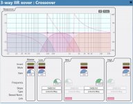
Here are the mag and phase traces of the three blocks.
I used only 4k taps for both the global IIR correction, as well as the linear phase summation. Hence the small deviations from ideal.
Also the IIR summation is a simple parallel summation as seen in the schematic, not a good Linkwitz cascade with all pass...so slight mag ripple there too.

here's the impulse responses.

But the FFTS can't show Step response, so the schematic has REW input and output, to get those graphs..
Here's the same block outputs as measured by REW.
IIR summed:
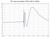
IIR summed with global FIR correction:
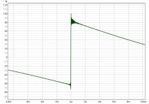
And linear phase xovers summed:
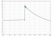
I tried global correction or IIR two ways: mag and phase correction, and phase correction only.
Both tries give the same step response.
So I dunno guys....do you see anything wrong, or doesn't make sense?
let me make a series of a few quick individual replies, and then I'll lay out in better detail what I did /am doing...
@Alex, hope I'm not leading you and others on a goose chase...i don't think so, but we'll see....
@charlie, yep, always the chance i did something wrong. price of self-eductation i guess. Thx for your willingness to look at what i've done. Btw, congrats on your PE win.
@KSTR, i can kinda follow your math, but not so fully that I feel i understand it gut level. I do get the idea of complex transfer multiplication though.
@Boden, yep
@Newvirus, I don't know how to do time reversed filtering...would like to learn
@wesayso, yep...inside rePhase I can do the same thing...when the entire final output is one filter that rePhase does all the complex filter summation along KSTR's point, I think.
However, when I apply a global FIR filter to a processing already in place, like an IIR DSP, or a passive or active analog speaker.....
or getting back to the electrical example I posted.....
I get measured results of the two processes in series, like I think would exist in real world global FIR correction .....that show pre-ring.
Happy to find out if i'm doing something/ thinking something / incorrect.
Ok, here's the test bed I've been using.
Qsys allows dual channel FFTs to be placed into the schematic for real time analysis, so I put one on each of three separate processing 'blocks':
The IIR xovers summed together block.
The IIR xovers summed together with global FIR correction, block.
And a block using linear phase xovers summed together.
The 3 FFTs are an easy way to show how mag, phase and impulse compare.
Here's the IIR xover again.

Here are the mag and phase traces of the three blocks.
I used only 4k taps for both the global IIR correction, as well as the linear phase summation. Hence the small deviations from ideal.
Also the IIR summation is a simple parallel summation as seen in the schematic, not a good Linkwitz cascade with all pass...so slight mag ripple there too.
here's the impulse responses.
But the FFTS can't show Step response, so the schematic has REW input and output, to get those graphs..
Here's the same block outputs as measured by REW.
IIR summed:

IIR summed with global FIR correction:

And linear phase xovers summed:

I tried global correction or IIR two ways: mag and phase correction, and phase correction only.
Both tries give the same step response.
So I dunno guys....do you see anything wrong, or doesn't make sense?
Take the 3 way IIR xover summed IR, left top from this picture:

and multiply it with the phaseLR file made in Rephase (the correction FIR file added to this post), that 'should' show the same result as your linear phase sum.
The math stays the same, hence the two same pictures as end result that I showed. If your processor adds ringing somewhere, that doesn't mean that the math of these filters isn't correct. The end result should be exactly the same between both methods. If it's not, look for a fault elsewhere.

The Rephase correction, just multiply this with the IIR sum. You may have had insufficient tabs in your FIR correction for this to happen?
and multiply it with the phaseLR file made in Rephase (the correction FIR file added to this post), that 'should' show the same result as your linear phase sum.
The math stays the same, hence the two same pictures as end result that I showed. If your processor adds ringing somewhere, that doesn't mean that the math of these filters isn't correct. The end result should be exactly the same between both methods. If it's not, look for a fault elsewhere.
The Rephase correction, just multiply this with the IIR sum. You may have had insufficient tabs in your FIR correction for this to happen?
Attachments
Mark,, firstly I suggest that you read what Mr. Berchin has written above (if you already didn't).@Newvirus, I don't know how to do time reversed filtering...would like to learn
The time-reversed filtering works like this (look up "block-based processing" if interested in knowing more).
- Digital data is mostly processed in finite-length blocks (packets), as opposed to processing one sample at a time. Most algorithms that we use everyday like FFT etc. are in fact block-based.
- Since a data block is what is passed on (as opposed to a data sample), the DSP has access to a few future samples within the block (represented as an array), allowing time-reversal operations required for zero-phase filtering (phase cancellation).
- When the processing on one block is done, the result is not only output but also used as "carry" (like in mathematics), by the next block being processed. Since all of this happens really quickly, the processing appears to be near "real-time", much like the processing of analogue signals, but it's actually quantised.
- The zero-phase technique works not only for FIR, but for IIR filters as well. Nevertheless, it cannot be implemented as an analogue circuit, as it requires knowledge of future information.
Last edited:
Continued thx to all guys,
@gberchin, yes to all you said....i'm pretty comfortable with all that
@newvirus, i can't write code, or use matlab, etc...do you know a software program/ technique with which i can implement time reversed filtering?
@wesayso, yep, I'm pretty sure I can do that and get the results you show in rePhase.
( if anyone cares, mdats are attached...change zip extension to mdat
It's been easy enough putting, IIR/ min phase and lin phase filters into a single FIR file with rePhase & FirDesigner. And even with using REW as a fir generator via impulse inversions, trace arithmetic, and multiplications.
That works fine for me, with minimal pre-ring, when all the filtering ends up in a single FIR file.
But what happens when you can't put it all into a single file?
So like in the example I've been posting, what happens when global FIR correction needs to be in series with existing IIR or passive implementations?
Because I think that's what global FIR correction comes down to, in real-world applications.
I mean, if you have a FIR processor to begin with, who the heck is going to use IIR xovers and then linearize them in the same FIR file, when all you have to do is use linear phase xovers to begin with. That's an illogical non-starter, imo.
I'm left thinking global FIR realistically means, applied to something already in place, externally in series, and can not be convolved/multiplied into one file.
I guess the question is: When we have to put filter blocks in series in separate processing stages, does the net filter of those in-series filter blocks, give the exact same transfer function as when the filter blocks are convolved/multiplied together into one filter?
Attachments
What I was trying to say that you can factor out terms in a transfer function and when you factor out common terms in a sum of two transfer functions they become global multipliers on the sum. The common term here is the phase contribution which is the same for the minimum-phase highpass, the lowpass and also, following, for the sum (which is not minimum phase).@KSTR, i can kinda follow your math, but not so fully that I feel i understand it gut level. I do get the idea of complex transfer multiplication though.
The point is that when we invert the common factor and multiply it with the equation the resulting common factor disappears as it now reduced to unity, making the sum linear phase. But you can just as well apply the inversion on both terms of the sum independently, getting two linear phase functions that also sum linear phase. It's the exact same thing.
Yes, and it is exactly the litmus test to verify the equivalence.I guess the question is: When we have to put filter blocks in series in separate processing stages, does the net filter of those in-series filter blocks, give the exact same transfer function as when the filter blocks are convolved/multiplied together into one filter?
- The zero-phase technique works not only for FIR, but for IIR filters as well. Nevertheless, it cannot be implemented as an analogue circuit, as it requires knowledge of future information.
For completeness I'll mention that zero-phase via time-reversal can only be approximated in the IIR case. The reason is in the name: Infinite Impulse Response. The response of an IIR filter extends to infinite time, so it has to be truncated at some point to make the time-reversed filter implementable.
A big reason that I think NOT to use global FIR on top an existing speaker setup, be it passive or active,
is to avoid pre-ring.
So basically this statement turned out to be true only for the way you used it, within your (test) setup, but the quote above suggests it's more of a 'universal truth'.
It all depends on the tools available, but global FIR on top of an existing speaker setup, be it passive or active, does not have to lead to more pré-ringing.
We wouldn't want to scare people away from trying. Pretty sure there's enough happy Rephase users out there that did exactly this. If people already have passive or active crossovers in place, that need compensating they can do so with a FIR filter on top. As long as they can reverse the phase these crossovers caused, there's no need to be extra worried about pré-ringing vs using linear phase crossovers. Both methods act exactly the same.(*) Pré-ringing is a fact with phase manipulation like this, as stated previously by @gberchin. But it needs to be mentioned that the (additional) pré-ringing as seen in the first post isn't caused by the method of applying a FIR filter after first applying IIR crossovers.
The fault is caused by something else.
(*) as long as it is applied correctly, obviously.
I may be worth noting that we need the root of a minimum or mixed phase phase filter which is then applied twice (multplied with itself) magnitude-wise but the phase portions cancel to zero phase because one pass is reversed in time vs the other. A LR4 is a perfect example because Linkwitz-Riley is by definition a squared Butterworth filter. I use this trick all the time for scratch FIR filter kernel, using a "dirac" single-sample pulse and apply IIR's on it, with second pass working on the time-reversed first pass.Mark,, firstly I suggest that you read what Mr. Berchin has written above (if you already didn't).
The time-reversed filtering works like this (look up "block-based processing" if interested in knowing more).
- Digital data is mostly processed in finite-length blocks (packets), as opposed to processing one sample at a time. Most algorithms that we use everyday like FFT etc. are in fact block-based.
- Since a data block is what is passed on (as opposed to a data sample), the DSP has access to a few future samples within the block (represented as an array), allowing time-reversal operations required for zero-phase filtering (phase cancellation).
- When the processing on one block is done, the result is not only output but also used as "carry" (like in mathematics), by the next block being processed. Since all of this happens really quickly, the processing appears to be near "real-time", much like the processing of analogue signals, but it's actually quantised.
- The zero-phase technique works not only for FIR, but for IIR filters as well. Nevertheless, it cannot be implemented as an analogue circuit, as it requires knowledge of future information.
- Home
- Loudspeakers
- Multi-Way
- Why not IIR filters + a global phase linearization by FIR