Every "voltage" is a measure of the voltage difference between two points.
potential difference, you mean.
When a voltage at a point is said to be at a given voltage without more precision, it is the potential difference between this point and another point taken as a conceptual reference, usually ground (or earth) by default.
Many apparent difficulties in electricity vanish when thinking of voltage as always being between two points and thinking of ground as a concept, full of imperfections in the reality it is supposed to represent.
Very well said
 😎 🙂
😎 🙂
Balanced power amps
I also have schematics for the Krell FPB series (200).
Fully balanced.
Not sure if I can post though.
I also have schematics for the Krell FPB series (200).
Fully balanced.
Not sure if I can post though.
The technical-Brian is an extremely clever circuit, 2xshuntfeedback, two independent servos, yet all within one circuit, the balanced OPS drive with two VBe's, one on each side of the folded balanced cascode is truly amazing.
Hi Guys
If the input signal is always balanced then there is no advantage at all to using a power amp circuit that is differential to maintain balanced output. One simply has to set the gains of the two paths to be equal, and with modern circuits and 1% resistors, the gain will be as close as is needed. All of the super amps are built this way, with an input circuit that accepts balanced/unbalanced inputs and drives the identical PA blocks out of phase.
True differential amplifiers are used by Stax as their ESL headphone drivers.
A major pitfall with differential circuits is that they tend to have unbalanced outputs if the input is unbalanced. Matched input impedance helps greatly with unbalanced signals, but it never quite gets completely balanced at the output. This is why all of the cross-coupled circuits and other things that look "mostly" balanced, all have a splitter at the input.
True differential circuits are much better suited to high open-loop gains than to the low gains required for audio PAs. So, a mic input stage is a good app, otherwise they are best left to instrumentation.
Balanced drive of the speaker is a very good thing as THD can be knocked down because the ground reference points are no longer being upset.
Have fun
Hi Guys
If the input signal is always balanced then there is no advantage at all to using a power amp circuit that is differential to maintain balanced output. One simply has to set the gains of the two paths to be equal, and with modern circuits and 1% resistors, the gain will be as close as is needed. All of the super amps are built this way, with an input circuit that accepts balanced/unbalanced inputs and drives the identical PA blocks out of phase.
True differential amplifiers are used by Stax as their ESL headphone drivers.
A major pitfall with differential circuits is that they tend to have unbalanced outputs if the input is unbalanced. Matched input impedance helps greatly with unbalanced signals, but it never quite gets completely balanced at the output. This is why all of the cross-coupled circuits and other things that look "mostly" balanced, all have a splitter at the input.
True differential circuits are much better suited to high open-loop gains than to the low gains required for audio PAs. So, a mic input stage is a good app, otherwise they are best left to instrumentation.
Balanced drive of the speaker is a very good thing as THD can be knocked down because the ground reference points are no longer being upset.
Have fun
And your point being?
Hi Guys
mr l you are being ambiguous. Lots of points related to the Qs from the beginning of the thread and comments throughout. What's your point?
Just because there are examples of differential amplifier circuits in production past or present does not mean that such an approach is a good one. Better performance is generally achieved as I described above.
Have fun
Hi Guys
If the input signal is always balanced then there is no advantage at all to using a power amp circuit that is differential to maintain balanced output. One simply has to set the gains of the two paths to be equal, and with modern circuits and 1% resistors, the gain will be as close as is needed. All of the super amps are built this way, with an input circuit that accepts balanced/unbalanced inputs and drives the identical PA blocks out of phase.
True differential amplifiers are used by Stax as their ESL headphone drivers.
A major pitfall with differential circuits is that they tend to have unbalanced outputs if the input is unbalanced. Matched input impedance helps greatly with unbalanced signals, but it never quite gets completely balanced at the output. This is why all of the cross-coupled circuits and other things that look "mostly" balanced, all have a splitter at the input.
True differential circuits are much better suited to high open-loop gains than to the low gains required for audio PAs. So, a mic input stage is a good app, otherwise they are best left to instrumentation.
Balanced drive of the speaker is a very good thing as THD can be knocked down because the ground reference points are no longer being upset.
Have fun
Just for my understanding: what exactly do you mean by a differential circuit? Any circuit having a positive and negative input terminal (neither of which is ground), a positive and negative output terminal (neither of which is ground) and some degree of common-mode rejection?
I would call a circuit with positive and negative input and output terminals differential with or without common-mode rejection, but I get the impression you mean something else, otherwise your first paragraph makes no sense.
Last edited:
Hi Guys
Marcel, your understanding of a differential circuit is correct and my first paragraph makes sense. Read the rest of them, too, since now you can read it three times !
A purely differential circuit is just cascaded diff amps, like the old tube preamp blocks by Mcknightly, and others. Those had the advantage of having input and output transformers where the input Tx assured balanced drive to both sides and the output Tx combined the outputs to eliminate supply noise while still providing a balanced output.
The details in my post regarding gain etc all apply to solid-state diff amps. Higher closed-loop gain is their forte and makes things like CMR easy to acquire with almost no effort. Like the tube counterparts, oscillation can be an issue and the old circuits used "neutralisation". Modern circuits run into DC issues and then need bandaids like servos.
If a balanced input is always available, then there is no need to use a differential circuit to have balanced outputs. Two identical gain blocks will do the job with ease. look at many of the super amps for examples of this.
Have fun
Hi Guys
mr l you are being ambiguous. Lots of points related to the Qs from the beginning of the thread and comments throughout. What's your point?
Just because there are examples of differential amplifier circuits in production past or present does not mean that such an approach is a good one. Better performance is generally achieved as I described above.
Have fun
Yes, all those points are covered here:
Fully differential amplifier - Wikipedia, the free encyclopedia
More effort is required-from a design and economical-point of view.
But, it can be done, has been done, and done quite well.
https://passlabs.com/
Hi Guys
I'm glad you've found something you like (Passlab).
It is not surprising that the posted circuit is unstable.
Have fun
I'm glad you've found something you like (Passlab).
It is not surprising that the posted circuit is unstable.
Have fun
And I think this is the problem
All your comments so far are critical (technical, fair enough), but not constructive and bordering on condescending.
Hi Guys
I'm glad you've found something you like (Passlab).
It is not surprising that the posted circuit is unstable.
Have fun
All your comments so far are critical (technical, fair enough), but not constructive and bordering on condescending.
Hi Guys
mr l - You said you liked Passlabs and I said that is good. I can see how I was way out line and offensive there. Sorry.
You posted a circuit that you said was unstable. I agreed that it looked unstable I can see how agreement might confuse you. Sorry again.
I can see too that you take anything you don't understand to be criticism. Obviously that is my fault as well. Sorry.
Have fun
My bad
I never said I liked Passlabs, that's your assumption (but for the record, I do)
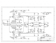
I never disagreed regarding the instability of the Ayre circuit, sorry.
Saying that there's no advantage to using a Differential power amp I see as a non-constructive criticism, sorry.
Saying that I don't understand it, is condescending.
I never said I liked Passlabs, that's your assumption (but for the record, I do)
I never disagreed regarding the instability of the Ayre circuit, sorry.
Saying that there's no advantage to using a Differential power amp I see as a non-constructive criticism, sorry.
Saying that I don't understand it, is condescending.
Hi Guys
So anyone who might know something you don't know is condescending if they try to tell you that information? Maybe you should try a different word, as I don't believe all of our teachers were condescending. You asked Qs that suggested you didn't know the answer. We all know different things and the forum is about sharing those things. You could drive a train through the gaps in my knowledge.
My experience with differential amplifiers is as I've stated it in my posts. There are two places to commonly use or attempt to use diff amps but only one of those applications makes the effort worthwhile. In my experience.
Have fun
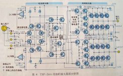
The Technical Brain is not a true differential amplifier.
A differential amplifier consists of two inputs and one output, as a minimum. It defines "differential amplifier" a circuit whose output signal is proportional to the difference between the two input signals multiplied by the gain of the stage. So if the two input signals are equal (and therefore the difference between them is zero), the output signal must be zero. If this statement is valid then the circuit posted is little differential.
I would describe this as balanced and then bridge connected .
In fact first stage seems a differential complementary stage but actually it is not.
It lacks the source coupling (via resistance or CCS) which is essential for the operation of a differential.
In fact, if you apply two identical input signals (common mode) then the signals on the drain of the fourth JFETs are not zero but equal (that is amplified in the same amount) that is its CMRR will be terrible.
Then at the exit of the folded-cascode, signals are converted in two single ended each of which pilot the six pairs of complementary output of each branch.
Finally, the two branches are connected in bridge mode to drive the load.
It generates power to the load in an optimal way until the two input signals are provided exactly equal and opposed (balanced).
Considering then the effort for its construction (6 power supplyes, 4 CCS and a quantity of transistors to be coupled with each other and with the respective complementary in quartets or more and without consider the power devices (24)) i would define the schema impractical and little smart.
- Status
- Not open for further replies.
- Home
- Amplifiers
- Solid State
- Why no fully differential circuits?