Now try plotting the output stage bias current against common mode voltage, my instinct is that smoke is possible from R1,2.
Regards, Dan.
Regards, Dan.
No fully differential circuits
Good question
Phono cartridges and tape heads are (by there nature) "fully differential" - yet very few manufacturers ever tried to make a balanced input preamp - remember that this would involve rewiring the tone arm.
Speaker crossover networks tend to be "unbalanced" but could also be designed "balanced".
Charles
Charles
Attachments
NO that is a single-ended VFA amplifier, but if you use two of them you can get something balanced
Hi,
fully differential, like Marantz MA9? Balanced, from input to output, with balanced feedback...
Sajti
fully differential, like Marantz MA9? Balanced, from input to output, with balanced feedback...
Sajti
NO that is a single-ended VFA amplifier
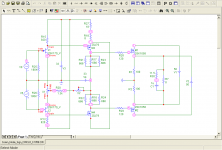
It's single-ended and thus not 'balanced', but AFAIK it is fully differential as it consists of two LTP's and two VAS stages.
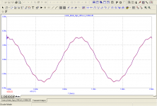
Now try plotting the output stage bias current against common mode voltage, my instinct is that smoke is possible from R1,2.
Regards, Dan.
Hi Dan, as the current flowing out of R1, R2 is proportional to the voltages on the nodes 3 and 6, I enclose transient analysis relating to the two nodes vs ground. The voltage on the two nodes is in phase with an amplitude of 5 microvolts peak.
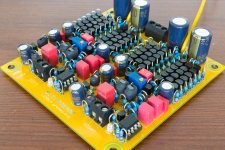
On the other hand, this circuit I've made almost 15 years ago, and I use it still. In particular, it was never necessary to change those two resistors.
Someone want that I place photos of the two mono amps?
Best regards.
Attachments
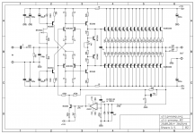
Hi Preamp, as a matter of interest - what is the idea behind using such an "array" of the small-signal transistors at the output follower?
Cheers,
Valery
I believe that the reason why fully differential amplifiers are rarely used is because they must be symmetrical.
Which is why the power stages are limited to two types (i think):
1 push-pull with output transformers (very little used in solid state)
2 just circlotron
BTW, for other examples see also this thread:
http://www.diyaudio.com/forums/solid-state/241272-what-do-sony-v-fets.html
Which is why the power stages are limited to two types (i think):
1 push-pull with output transformers (very little used in solid state)
2 just circlotron
BTW, for other examples see also this thread:
http://www.diyaudio.com/forums/solid-state/241272-what-do-sony-v-fets.html
It's single-ended and thus not 'balanced', but AFAIK it is fully differential as it consists of two LTP's and two VAS stages.
You are wrong, your circuit is complementary, not symmetrical, sorry. See post 30.
Also if there are 2 complementary differential stage the two main signals from input to output are in phase, so....... single-ended! 😀
Yep, that is another problem with "balanced all the way through." The gain of the positive and negative paths must be matched to unusually high precision (using components matched to, say, 0.1 percent or better in EVERY position that affects gain - this costs real money for high precision parts or real time in matching lots of extra parts) to maintain good CMRR....
Ensuring near zero common mode gain is one of the many reasons to unbalance early in the design.
Regards, Dan.
With the usual instrumentation-amp balanced input, you only need a very few well-matched resistors to get high CMRR. The ground currents on a well-laid-out PCB won't have a measurable effect on the "unbalanced" signal between the input and the output.
Unbalancing is the first thing done with (I presume "early in the design" actually means "early in the signal path") an input to a box, and for a balanced output, the "balanced output generator circuit" is the last thing in the signal path before a signal goes back to the outside world.
I agree. The reason of "why" may be mostly because of ease of design and lower cost of single path stages; and not better performing of many differential stages.Good question
By nature, every voltage is differential.Phono cartridges and tape heads are (by there nature) "fully differential"
Hi Preamp, as a matter of interest - what is the idea behind using such an "array" of the small-signal transistors at the output follower?
That is my approach to make some use of the remaining parts after matching the input pairs 😎.
You are wrong, your circuit is complementary, not symmetrical, sorry. See post 30.
Also if there are 2 complementary differential stage the two main signals from input to output are in phase, so....... single-ended! 😀
Okay, okay... 😱 😀
I agree. The reason of "why" may be mostly because of ease of design and lower cost of single path stages; and not better performing of many differential stages.
By nature, every voltage is differential.
Every "voltage" is a measure of the voltage difference between two points.Tell me more.
Bongiorno's SUMO amps *might* qualify... not certain that every stage was in fact differential though?
Unbalancing is the first thing done with (I presume "early in the design" actually means "early in the signal path") an input to a box, and for a balanced output, the "balanced output generator circuit" is the last thing in the signal path before a signal goes back to the outside world.
By early I did indeed refer to the signal path, as in right after the RFI filters and common mode choke, but I hate the whole 'signal path' notion as it tends to ignore at least half and often more like two thirds of the bits that matter, not just the current in the 'ground'but also how this gets back to the appropriate power rail, these details are not IMHO meaningfully separable from the notion of a signal path (More like a series of "signal loops").
Mixing desks of the old school analogue sort sometimes did a rather odd differential scheme with the summing amplifiers but that was often the one place you saw differential (But usually not balanced!) signalling inside a box.
Regards, Dan.
One of National's customeres was going to use the LM4702's in a new fully balanced high end power amp design. (The LM4702 was the first part in what became the LME series of analog audio parts built on a high voltage/low noise/low THD semi process.)
I heard the proto amplifier at Classe' Audio many years ago and it was incredible. It never made it to market though...as far as I know. So for a fully balanced power the LM4702 dual part is a good choice. (See AN-1490 on the TI website for notes on how to use that part...to bad TI removed the names of the National Semi Authors from all of the ap notes. I know the guy who wrote that ap-note ;-) )
audioman54 / Mark
Completely differential circuits are quite common in analogue IC design. Advantages: cancellation of even-order distortion, low sensitivity to anything common-mode, like supply ripple, substrate interference, ground voltage drops et cetera, well-defined signal return paths.
I usually don't make domestic hobby audio circuits balanced because it tends to make them more complicated and they usually have to interface with unbalanced consumer equipment anyway. You can find an exception here:
http://home.kpn.nl/verwa255/esl/amp.zip
Another exception is this balanced to unbalanced and vice-versa converter that I made for a semi-professional local radio studio:
Attachments
Last edited:
- Status
- Not open for further replies.
- Home
- Amplifiers
- Solid State
- Why no fully differential circuits?