I'm trying to get my head around the coupling caps. I do understand that their purpose is to block the DC component of the signal however what I don't understand is why would the line output of a DAC have DC at all?
I could also put a cap just in case but considering that a line-in is around 10K of impedance, I would need a 1u cap and I can only find them in polarized type for SMD. Would a polarized cap work as intended in the absence of DC bias?
I could also put a cap just in case but considering that a line-in is around 10K of impedance, I would need a 1u cap and I can only find them in polarized type for SMD. Would a polarized cap work as intended in the absence of DC bias?
If it's a DAC circuit with a single supply, it probably has a DC bias voltage greater than the peak signal voltage, so it can handle the maximum negative signal excursion without negative supply.
If it's a circuit with a symmetrical supply, chances are that the output is nominally biased at 0 V, but due to component tolerances and mismatch, it will never be exactly 0 V. Whether you then need a DC blocking capacitor depends on how well the circuitry downstream can handle small offsets.
Polarized aluminium electrolytic capacitors can handle negative voltages down to -1.5 V or so. Tantalum electrolytic capacitors are far worse at handling negative voltages.

Bipolar electrolytic caps (or 2 polar electrolytic caps in series) or, one of the best choices really, large value film caps can also be used.
DC servos can be used but are more complex and often generate ear piercing DC offset at power on/off which then requires muting.
* BTW you need 4.7 uF which is easily available in 5 mm pitch MKS/MKT. Forget about SMD, through hole film caps win hands down from X7R and most SMD polarized electrolytic caps.
Last edited:
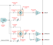
It's single supply (datasheet) and has 2 outputs. A mono output for line out and a mono differential speaker output which is also (according to the datasheet) can be used to drive a headphone.If it's a DAC circuit with a single supply, it probably has a DC bias voltage greater than the peak signal voltage, so it can handle the maximum negative signal excursion without negative supply.
If it's a circuit with a symmetrical supply, chances are that the output is nominally biased at 0 V, but due to component tolerances and mismatch, it will never be exactly 0 V. Whether you then need a DC blocking capacitor depends on how well the circuitry downstream can handle small offsets.
Polarized aluminium electrolytic capacitors can handle negative voltages down to -1.5 V or so. Tantalum electrolytic capacitors are far worse at handling negative voltages.
Which brings another question. I originally omitted this from my original post but, apart from the line out, I'm also looking to have a headphone output and given the headphones impedance range, the coupling capacitor size becomes huge (1000-2000 uF).
To drive the single channel of a headphone, the datasheet claims that I should tie the negative end of the differential speaker output to the ground and use the positive end of the signal to drive the headphone. As you mentioned I assume the positive signal in this case DC biased.
However on the datasheet I've noticed this explanation
Does that mean I can tie the mono output to the headphone ground and not need the huge coupling caps?
I'm very new to this sorry if I'm not making any sense.
Attachments
I guess that is indeed what is meant.
You could try to find application notes for this IC. Those are usually more explicit about what the chip designers intended to be connected where and why than datasheets.
You could try to find application notes for this IC. Those are usually more explicit about what the chip designers intended to be connected where and why than datasheets.
Last edited:
Unfortunately not much examples/application notes.
Since I'm going to want to use both the headphones and line out at the same time, I don't think I can use it.
Vref, according to the datasheet is Vdd/2, can't I just have a voltage divider to my Vdd and tie it to the headphone ground?
Since I'm going to want to use both the headphones and line out at the same time, I don't think I can use it.
Vref, according to the datasheet is Vdd/2, can't I just have a voltage divider to my Vdd and tie it to the headphone ground?
I read the datasheet as saying there's a bridged speaker output (8 ohms or more) and another single-ended output able to drive a headphone load (16 ohms of more) or line out. The single-ended output needs a DC blocking capacitor.It's single supply (datasheet) and has 2 outputs. A mono output for line out and a mono differential speaker output which is also (according to the datasheet) can be used to drive a headphone.
I remember those days when I played with various combinations and types of coupling caps... The best electrolytic-capacitor-type result I obtained was with two polarized back-to-back capacitors (to mimic a non-polar type), BUT with the middle point tied to either Vcc or Vee... electrolyte likes to see some DC across the plates. The next best thing was a non-polar type... but I could not do the trick to bring its electrolyte to a proper state by introducing some voltage to either plate...
Electronics aren’t perfect, and often during turn-on there’s a situation where briefly, a burst of dc goes through.I'm trying to get my head around the coupling caps. I do understand that their purpose is to block the DC component of the signal however what I don't understand is why would the line output of a DAC have DC at all?
I could also put a cap just in case but considering that a line-in is around 10K of impedance, I would need a 1u cap and I can only find them in polarized type for SMD. Would a polarized cap work as intended in the absence of DC bias?
Also can be a benefit maintaining isolation of the potentially long interconnect cables, which can feed interference.
You don’t want the minimum value either, as mentioned, 4.7uf would be desirable.
A polarized cap will work at the low voltages seen in typical line level coupling, breaking the rules so to speak. Has been done for decades in probably millions of consumer devices.
- Home
- Source & Line
- Digital Line Level
- Why is DAC output coupling needed?