Not to forget the arrival of the Ongaku, in the early 90's, immerging from the mists (of solid state rack systems), like a mysterious ship, 211 glowing suggestively of arcane eastern sensual delights.
So is it safe to assume that any distortion that might be caused by the zero crossing is linear and not detrimental to small signals.
That's the million dollar question. Distortion is by definition non-linear, but your question could maybe be otherwise phrased as: does the near-zero-crossing "non-monotonicity" of permeability (the slope of the B-H curve) of conventional steel cores *significantly* affect transfer linearity?
For the (ideal) transformer itself, no. Maybe surprisingly, the output transformer itself is still (ideally) linear through this region. Inductance appears "outside" the transformer.
Permeability affects inductance, as do a gazillion other things including moon phase, so becomes important when inductance becomes important
My personal opinion is that amplifiers need to be very linear at 75dB SPL at listener's ears, be capable of +20dB peaks (or to overload very cleanly) and be monotonic down to below any real world noise level. That last requirement is the toughest.
YOS,
Chris
Last edited:
Rod Coleman,
yes, huge orchestra, more than 100 instruments, advanced tonality and great depth - the creation of a very great man.
yes, huge orchestra, more than 100 instruments, advanced tonality and great depth - the creation of a very great man.
Bravo. This piece is the only instance of an advance beyond the Mahler symphony, in my personal perception. Terrifying!
Yes, but practically speaking, nobody is going to listen to an opera at its correct theatre volume in an average listening room. Or if they do they live in a mansion. It's all going to be at a reduced volume. Since this is the case anyway, I prefer my opera on a SE amp because I want to bring out the full vocal colour of the singers and the timbre of the orchestral instruments. I know very well what orchestral instruments sound like because I'm a musician trained in a conservatoire and played in orchestras for years. It's all about timbre for me.
And yes, I regularly listen to the Ring Cycle, Meistersinger, Parsifal, L'Enfant et les Sortileges, all the Janacek and R.Strauss operas and so on.
And I have to say that the loudest live music I've witnessed is all amplified jazz and rock rather than opera. The Duke Ellington or Basie bands aren't trivial at full volume. Probably louder than most of Debussy's Pelleas and Melisande.
I am very fortunate in that I attended a Count Basie Orchestra concert led by Frank Foster about thirty years ago. At that time the members had all been hired by Basie himself. At least one of the members (bassist) had been with the group since the 50’s.
The loudest live music I've heard caused permanent hearing loss... I don't understand the concept of "hi-fi ear plugs" to make an event not be deafening...
I'm very, very confused by this. Perhaps if it were restated for us slower folks.
YOS,
Chris
Chris: for signal to appear on tube input, it has to be applied between grid and cathode. AC filament voltage is NOT applied between grid and cathode, it is applied to cathode only.
Bravo. This piece is the only instance of an advance beyond the Mahler symphony, in my personal perception. Terrifying!
Shostakovich's 6th may rival 4th in brutal dissonances and harshness. My favorite though is 7th, maybe because my father is a survivor of the blockade of Leningrad. Sorry for going off-topic.
Last edited:
I like his 15th, but the guy was a prolific genius. Funny, I have no problem with the dissonance, I find it "interesting"
Last edited:
Hysteresis at “zero crossing”
For reasons related to field coil loudspeaker driver design and construction, I have spent time examining and dealing with magnetic hysteresis, particularly the ‘zero crossing’ kink. In a field coil driver, the magnetisation path is the tapered hysteresis loop in Dave’s diagram with its locus (centre of area) lying over the origin (the point [0,0]). In my experience, the ‘kink’ is hardly evident, as the magnetisation curve is almost never at [0,0] in the presence of any signal (even very very small, musical or otherwise). What is evident is the distortion generated by the signal travelling around the hysteresis curve – for small signals, it’s proportional to the signal level and inversely proportional to permeability (big signals can put the extremes of the hysteresis curve into saturation and proportionality evaporates). Symmetry around [0,0] tends to reduce even order harmonics.
In push-pull amplifiers, the locus of the OPT hysteresis curve is at [0,0] when the anode currents of the output valves are exactly equal at the operating point – as with closely matched valves. And it would stay there if the valve characteristics were matched at all signal levels. I have never quite experienced this. In practice, each valve is a bit different including differences in rectification when dealing with a signal - feeding the valves a signal usually produces a measurable DC offset across the primary of the output transformer when, at idle, there was almost none (RDH4 addresses this phenomenon). The offset varies with signal magnitude and (often) frequency. The locus of the OPT hysteresis curve therefore wanders around [0,0]. Symmetry (and cancellation of even harmonics) varies somewhat with frequency and signal level. I don’t want to exaggerate this – 2nd order cancellation is evident even when the signal starts to saturate the OPT.
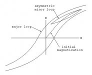
Single ended amplifiers show an analogous effect. At idle, the standing DC in the OPT primary places the magnetisation at some point [A,B] on the B-H curve. Once a signal is imposed, the magnetisation travels around what is called a ‘minor hysteresis curve’ in the upper right quadrant of the magnetisation curve (see the illustration attached) roughly centred around the point [A,B]. I say roughly because the output valve will to some extent rectify the input signal, moving [A,B] to some new point on the magnetisation curve (measurable as a DC change in operating point) that depends on signal magnitude and frequency. Importantly, the minor loop is asymmetric and the resulting output includes both odd and even harmonics. Most single ended OPTs are designed so that the idle locus [A,B] is in the upper right portion of the B-H curve. In practice, large signals tend to induce saturation in the upper right portion of the minor hysteresis curve well before the lower left portion approaches [0,0].
On Shosty’s 4th – I have sometimes used it as a benchmark because if the system is right, it’s terrifying and disturbing and a most magnificent train-wreck visited on the sonata form. Mostly, I just listen to it to grapple with the darker side of human endeavours - as you say, Rod, the creation of a great man. Rozhdestvensky (1988) on Melodiya for LP or Myung-Whan Chung (2002) on DG for CD.
For reasons related to field coil loudspeaker driver design and construction, I have spent time examining and dealing with magnetic hysteresis, particularly the ‘zero crossing’ kink. In a field coil driver, the magnetisation path is the tapered hysteresis loop in Dave’s diagram with its locus (centre of area) lying over the origin (the point [0,0]). In my experience, the ‘kink’ is hardly evident, as the magnetisation curve is almost never at [0,0] in the presence of any signal (even very very small, musical or otherwise). What is evident is the distortion generated by the signal travelling around the hysteresis curve – for small signals, it’s proportional to the signal level and inversely proportional to permeability (big signals can put the extremes of the hysteresis curve into saturation and proportionality evaporates). Symmetry around [0,0] tends to reduce even order harmonics.
In push-pull amplifiers, the locus of the OPT hysteresis curve is at [0,0] when the anode currents of the output valves are exactly equal at the operating point – as with closely matched valves. And it would stay there if the valve characteristics were matched at all signal levels. I have never quite experienced this. In practice, each valve is a bit different including differences in rectification when dealing with a signal - feeding the valves a signal usually produces a measurable DC offset across the primary of the output transformer when, at idle, there was almost none (RDH4 addresses this phenomenon). The offset varies with signal magnitude and (often) frequency. The locus of the OPT hysteresis curve therefore wanders around [0,0]. Symmetry (and cancellation of even harmonics) varies somewhat with frequency and signal level. I don’t want to exaggerate this – 2nd order cancellation is evident even when the signal starts to saturate the OPT.
Single ended amplifiers show an analogous effect. At idle, the standing DC in the OPT primary places the magnetisation at some point [A,B] on the B-H curve. Once a signal is imposed, the magnetisation travels around what is called a ‘minor hysteresis curve’ in the upper right quadrant of the magnetisation curve (see the illustration attached) roughly centred around the point [A,B]. I say roughly because the output valve will to some extent rectify the input signal, moving [A,B] to some new point on the magnetisation curve (measurable as a DC change in operating point) that depends on signal magnitude and frequency. Importantly, the minor loop is asymmetric and the resulting output includes both odd and even harmonics. Most single ended OPTs are designed so that the idle locus [A,B] is in the upper right portion of the B-H curve. In practice, large signals tend to induce saturation in the upper right portion of the minor hysteresis curve well before the lower left portion approaches [0,0].
On Shosty’s 4th – I have sometimes used it as a benchmark because if the system is right, it’s terrifying and disturbing and a most magnificent train-wreck visited on the sonata form. Mostly, I just listen to it to grapple with the darker side of human endeavours - as you say, Rod, the creation of a great man. Rozhdestvensky (1988) on Melodiya for LP or Myung-Whan Chung (2002) on DG for CD.
Attachments
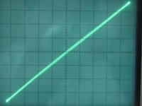
In praxis, the curve becomes almost a single straight line.
Certainly for OPTs with a significant air gap in the core.
SE and PP transformers BOTH go through zero crossing of the magnetization curve. What DC magnetization causes is not moving the operating point to a more linear area, but moving the whole B-H curve upwards and squeezing magnetization headroom. The analogy with tube DC biasing for Class A is wrong here.
Transition through zero magnetization has no "kink", it is straight line.
Transition through zero magnetization has no "kink", it is straight line.
Yes, but practically speaking, nobody is going to listen to an opera at its correct theatre volume in an average listening room.
I do. Every day.
With single ended triodes and 110dB/w/m horns. I generally know where to set the volume control to get accurate 105dB peaks for piano fortissimo...sounds wonderful at real world sound levels...
And whenever you think there is no one doing like this, someone like Zieten comes right out of the bush and teaches you that it's him. 😀 (german saying).
Last edited:
The real 300B is a legend and unobtanium.I think the 300B tube made single ended amplifiers attractive.
There are replica tubes (mostly asia, china), which pretend to be 300B tubes but never made to proove it. Every test they have performed, those replicas failed.
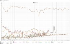
It's measurable. Two distortion plots below, a bench 6LU8 pentode SE into an old PSB Alpha Mite. The only difference between the plots is flipping the speaker phase. A pretty intuitive result obscured by decades of audiophile bun fights.Correctly phased, H2 of SE amp can cancel some of speaker generated H2 producing less total acoustic distortion. Works for single driver or multi amp with LLXO setup.
Attachments

- Home
- Amplifiers
- Tubes / Valves
- Why has single ended output become popular