Yes, this is pretty much what Kohl 1960 p246 says too, so as to avoid the build up of low work-function surface films.Rod Coleman cited Beck, who said "..the barium evaporated from the cathode diffuses into the gold instead of remaining on the surface."
In A Manual of Materials for Microwave Tubes, Thornburg D L, Thrall E S, & Brous J, RCA 1961, in says on page 63: "Gold internal surfcaes are preferred for tubes with oxide or matrix cathodes; evaporated barium will diffuse away from the surface into the metal".
Thus the virtue of gold is that barium atoms readily diffuse into it, where they cannot emit electrons, leaving the surface clean.
There still seems a few loose ends though, because one might then predict that progressive use might well saturate the Au grid coating, and that more than a token plating thickness be of merit ........ neither of which seems to apply?
Sy, you could check this in any basic textbook on tube making.Question that I truly don't know: I've only been in one tube manufacturing facility, and it sure didn't look like they were handling the oxide-coated cathodes in a vacuum. Ladies on the assembly line had a pot of some oxide paint and applied it to the cathodes right at their workstations.
Barium oxide and Strontium oxide are hopelessly unstable in area - won't last an eyeblink. They are stable only if oxygen is pumped out of the tube to hard vacuum levels.
What they do is coat the cathode tubes in a mix that contains the corresponding carbonates (BaCO3 & SrCO3) and an organic binder medium (ie so that is an easily handled slurry). Water can be used, but is not ideal.
First, one or more coats of the mix are applied to the cathode. This can be done in air, so it is.
Next, is the initial bake, done in air. The intital bake is low temperature and serves to evaporate nearly all the binder /medium, leaving a dried coating of the carbonates.
After assembly of the coated cathode with the rest of the tube electrodes, getter, micas, etc, the assembly goes into the glass.
Then, the glass is vacuum-tight sealed onto a sealex machine (seal and exhaust).
Most of the air is pumped out. Then, the cathode is heated at a relative low temperature (using the heater or RF induction), low compared to final operating temperature but higher than the intial bake-out while pumping continues. During this process the carbonates are converted slowly into oxides (BaO & SrO), liberating CO2 and O2. The sealex machine sucks out the CO2 and O2, as fast as they arise, along with any residual H2O remaining after the initial bakeout.
Finally, pump-out is done, and the tube glass sealed off and separated from the sealex machine. What we have now is a tube partly gassy with the last of the O2 and a cathode coating that is porous and containing almost nothing but BaO and SrO. Left for a while in this stae, the O2 would go back an convert some oxides back into carbonates, except the carbon's gone.
The getter is now fired by RF induction, getting rid of the last of the oxygen. The heater is run at a high temperature for a while to complete activation (ie get rid of any lingering carbonates, diffuse metal atoms)
Most decidedly yes! What factory was this? In what country? What tube type? I've watched a few videos of tube making in former iron curtain countries, and in China. The things they do are quite horifying.Was this atypical?
In reputable firms like Mullard, RCA, etc, tube making was very highly automated - it had to be, due to enourmous production volumes.
The thing is, the thickness of the oxide coating is critical to both correct tube performance and long life. A common method used in consumer tubes was a carefully controlled spray process (like automated spray painting). In small directly heated tubes, the thickness of the oxide coating is even more critical.
In manufacture of directly heated tubes, a method known as slip coating was commonly used - a machine pulled the heater wires through a tub of carbonate mix - controlled mix viscosity, controlled pulling speed, controlled length in the tub, etc. Certainly no girl with a pot of gloop.
Last edited:
That's exactly what happens.There still seems a few loose ends though, because one might then predict that progressive use might well saturate the Au grid coating,
No, it certainly does apply. A definite thicknes is required, so that the grid lasts at least as along as the cathode in typical service.and that more than a token plating thickness be of merit ........ neither of which seems to apply?
The Thornburg book I quoted does go on to say that the gold plating can only soak up the barium for so long. Once it is saturated, grid current rapidly rises.
The question is - how thick does the gold need to be, to outlast the cathode? I have no idea on that one. I could look up the saturation concentration, but papers covering the diffusion of metals into metals are not exactly common - and that's only half the answer anyway.
In what country?
New Jersey! Circa 1968, I was a wee lad with an addiction to building ham radio gear.
Appreciate the other background.
It is not the oxide that does the electron emitting. He can get the work function of Sr and Ba from standard tables. The values are:-
Ba........2.52 eV
Sr........2.59 eV
We might thus expect, in a cathode mix containg about equal proportions of BaO and SrO, that the cathode will have a work function of 2.55.
Real cathodes do somewhat better, appearing to have a work function lower than 2.55.
I would not be so sure.
Indeed, BaO-SrO has a work function of about e φ = 1 eV, and its Richardson constant is amazingly low, about Ao = 10 A/(m² ºK²)
Reasons include the following, in descending order of importance:-
1) Oxide cathodes have, on a microscopic scale, a very rough surface. The emission of electrons is similar in physics to the emission of atoms (evaporation). In both cases surface roughness improves emission.
2) Tube manufactuers discovered various proprietry ways of doctoring the carbonate mix to make it work better; they discovered that some metals when used for the cathode sleeve improved things (eg nickel);
3) Schottky effect slightly improves emission - because the voltage gradient within the cathode matrix accelerates electrons toward the surface, it reduces the amount of energy that has to be sourced from heat to ovecome the work function barrier. Popilin was right in principle, he was just wrong on the magnitude of the effect, which is small (few percent)
You are underestimating Schottky effect and the electric fields involved.
Measuring work functions of cathode and anode of a 5R4GY, I used
Js = Jo exp [(α √ Va ) / ( k T )]
Comparing with
Js = Jo exp{e √[e E / (4 π ε0)] / k T}
We find
E = 4 π ε0 α² Va / e
From experimental results
α ≈ 7.74 x 10⁻³
Then, for a tiny Va = 60 V
E ≈ 2.5 MV/m

It means about double emission.
Nah, mate, its hard to measure the work function of metal oxides like BaO and SrO because they are hopelessly unstable when not in a hard vacuum.
I have no idea about the oxide cathode composition of 5R4GY, but if it is BaO-SrO, my result
e φ = (0.9 ± 0.2) eV
Not too bad for a couple of multimeters, a picoammeter, and two PSUs. 😎
Last edited:
keep the dialog open
There are many things going on inside the envelope at the same time. There are many theories and piles of test data.
In the real world, as in Edison’s lab, things were done empirically by scientists, engineers and experimenters. Life testing was done at the M.I.T. Radiation Laboratory among other places. Failures of grids, cathodes and arcing deaths were observed. Manufacturing and testing standards were developed. JAN tube specifications were written. Still to this day people are discussing theory and mathematical formulas in an effort to explain things that we do not clearly understand. If tubes are pushed beyond the specifications, as we all do, interesting things happen.
Then there are the humans involved. Not everyone may have a handle on the intricacies of a particular theory. Then again that particular model may breakdown outside of the standardized operation and testing procedures. Say operating a gold coated grid above 700C, or skewing the cathode work function calculation because of an anode voltage change. Yes the Schottky effect lives. Everyone has something of value to add, if not they may serve as a bad example to others and be an object of ridicule. (joke)
My friend teaches computer programing. He is very careful when critiquing someone’s work not to tell that student how stupid he or she is but to carefully tell them the problem with the computer code. This keeps the dialog open.
DT
Last edited:

There's a good reason that diffusion rates of alien metal atoms within a metal lattice isn't well documented - it doesn't happen to any notable extent........and yet there are a number of respectable references that suggest absorbtion of cathode material by gold here. How intriguing.The question is - how thick does the gold need to be, to outlast the cathode? I have no idea on that one. I could look up the saturation concentration, but papers covering the diffusion of metals into metals are not exactly common - and that's only half the answer anyway.
Whether the process is then effectively 'alloying', I suspect it may be - if it happens.
To address how thick the gold layer needs to be, Baker 1953 Brit Jrnl App Phys 4,10 abstract states : Emission measurements have been made on gold-plated molybdenum and gold-plated manganesenickel grids in the presence of an oxide-coated cathode. For grids which cannot be designed to operate below 350°C, a minimum thickness of 1 μ of gold will suppress grid emission. Silver is not so reliable, but is effective in some cases.
The answer might lie in the full article, if anyone feels willing to pay the pound of flesh to download it in full. I can likely get it gratis from the British Library, but not for a while.
1 micron seems pretty much a spatter thickness, perhaps a few thousand gold atoms or so. This hardly seems like much of a reserve, or a good hiding place for lost Ba/BaO molecules.......... on the basis of these loose ends, I have reservations that absorbtion holds the answer - despite the papers which assert it.
I haven't given up on catalysis. Seems gold can be a reduction catalyst, and there is an oxide involved. But, hands up, chemistry is really not my strong suit, but we know a man here whose it is ........... just that, to me, a spatter trace being effective over a long period kind of shouts catalysis. What could the reduction reaction be, where would the oxygen and barium go ? Does the barium ion somehow return to the cathode and the oxygen ion to the anode ? Getter?
Interesting.
1 um is pretty thick, for all intents and purposes. Density doesn't change too much from ordered to amorphous and you can *roughly* call a lattice parameter (based off bulk density) of d=0.257 nm--rounding to .25 to make math easier, that's 4000 atoms thick.
I rarely used Noble metal thicknesses coatings thicker than 200nm for my (semiconductor-based) work. At 350 °C, are we getting any sorts of eutectic effects with any of the metals listed? I haven't looked.
I rarely used Noble metal thicknesses coatings thicker than 200nm for my (semiconductor-based) work. At 350 °C, are we getting any sorts of eutectic effects with any of the metals listed? I haven't looked.
Pretty much. Not wishing to split atoms, the site below reports the lattice constant for Au to be about 0.41 nm, that gives about 2500 atoms thickness. Just somehow seems too thin to progressively stuff away Ba/BaO molecules without saturation, via a diffusion process that I'm not convinced has any viable rate? For a tube life of 2500 hours, 1 molecule per hour per lattice unit surface area might result in a 50% homogenous alloy, if we are to believe - perhaps, dunno, seems slow, if it's even possible to have intuition about such things...in the context of the avagadro number 6E+23......?Density doesn't change too much from ordered to amorphous and you can *roughly* call a lattice parameter (based off bulk density) of d=0.257 nm--rounding to .25 to make math easier, that's 4000 atoms thick.
Lattice data :
Technical data for the element Gold in the Periodic Table
The answer might lie in the full article, if anyone feels willing to pay the pound of flesh to download it in full. I can likely get it gratis from the British Library, but not for a while.
Drop me an email, I may have a copy of it.
I'm skeptical of the catalytic idea- gold is pretty inert as these things go. If catalysis were the goal, there's more active materials like Pd and Pt.
Sy seems to have some misconceptions here. It is not the oxide that emits electrons.
Yes and no, in that order, nah, it is a joke. 😀
Let's suppose that Ba and Sr only contributes with emission, for Ba
e φ = 2.52 eV, ..... Ao = 0.06 A/(cm² ºK²)
Then, at T=800 ºK
Jo ≈ 5.1 x 10⁻¹² A/cm²
It is entirely negligible for a contaminated grid, I cannot find Ao for Sr, but I guess a similar result.
At 1000 ºK
Jo ≈ 1.19 x 10⁻⁸ A/cm²
Useless for a cathode. These results are against your argument.
Last edited:
.....Just somehow seems too thin to progressively stuff away Ba/BaO molecules without saturation, via a diffusion process that I'm not convinced has any viable rate?
It isn't BaO molecules the gold has to absorb. Just Ba atoms.
Because what gets evaporated from the cathodes is just Ba atoms (and Sr atoms).
Ultimately of course, that would leave the cathode with an excess of O. O diffuses through the cathodes coating porosity and ends up being recomboned in the getter flash.
Indeed, BaO-SrO has a work function of about e φ = 1 eV, and its Richardson constant is amazingly low, about Ao = 10 A/(m² ºK²)
Data source? Reference?
You are the one misunderstanding Schottky effect and the electric fields involved.
By Va, presumably you mean anode voltage wrt cathode. The anode voltage cannot possibly have any effect on what processes go on inside the cathode. I would have thought that obvious.
Do you think there is a little gopher inside the cathode coating? Perhpas he puts his head out now and then, and says "Hell! they put a big volatge on the anode, better spay around some more electrons.
In any vacuum tube, there is a division of potential. A relatively large potential drop between the cathode emission surface and the anodes. If the cathode is a pure metal cathode, that's pretty much all there is. You cannot have an electric field within a good conductor.
But in an oxide cathode, there is a small potential drop between the cathode metal base (the sleeve, or tape in the case of 5R4 & similar) and the emission (top) surface of the oxide layer. Because the oxide layer is anything but a good conductor - fortunately the thickness is only micrometers.
Ignoring any interface layer problems, the external voltage drop of the tube is the sum of these two potental drops: The drop across the vacuum, and the much smaller drop within the oxide layer.
It is the smaller drop within the oxide layer that accelerates electrons within it and thereby leads to schottky effect.
The electric field between anode and cathode top surface can only, obviously, affect electrons already emitted and within that space.
Last edited:
New Jersey! Circa 1968, I was a wee lad with an addiction to building ham radio gear.
1968! So presumably no need to worry about someone's reputation after all those years!
I presume they were making some very low sales volume tube, probably not a type that hams would be interested in.
Whose factory was it?
Some major tube makers did make certain very old types in very low volumes, using old methods. The Boonton Radio Co devised a very good Q meter in the 1930's - the 160A. It was so good they were still making it with a minor facelift and the same circuit in the 1960's (170A), when HP owned them. The design depended on a particular 1930's triode used as a detector. Finally, Western Electric said to them, "we are not making that ancient top cap grid 535A triode any more! The chap that's been doing it has retired, having been hand-making a 100 or so each year." So HP hired the Japanese to quickly design an all solid state replacement Q-meter - the HP4342A.
Here in Australia, when AWV were making millions of 6AQ5's, millions of 12AT7's and millions of a few other types, they made about 50 a year of type AV44. This is an edison diode - a diode used in the regulation of high power AC voltage systems, pretty much evers since Edison discovered thermionic emision and realised it can be used as non-linear regulator.
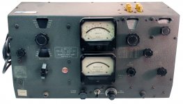
I own a Boonton Radio 170A Q-meter, in as-new condition. It is a beautiful instrument to use. But when that triode gives up, the whole thing is a write-off. The triode is the only part you cannot buy.
Last edited:
I owned a couple of Boonton 260A Q meters that used that same tube. It was sometimes selected from type 1659 or 2A6 I think. Because the grid leak resistance was so high (100 megohms) low grid capacitance and low grid current was a must. Like an electrometer tube. I think I may still have a couple stashed away in my attic somewhere. But it was the thermal couple that you had to be very careful of. If you lost that, the instrument was gone. And BTW, there was no gold in those tubes. At least none I could see.I own a Boonton Radio 170A Q-meter, in as-new condition. It is a beautiful instrument to use. But when that triode gives up, the whole thing is a write-off. The triode is the only part you cannot buy.
Attachments
I've heard worse explanations............seems there was a decades long struggle to explain oxide coating emission, the history of which is set out in Hermann /Wagener The Oxide Coated Cathode 1951 pt 1 Ch1.Do you think there is a little gopher inside the cathode coating? Perhpas he puts his head out now and then, and says "Hell! they put a big volatge on the anode, better spay around some more electrons.
The upshot of which, according to Hermann/Wagener is that an activated oxide cathode emission layer is a semiconductor material, essentially BaO doped with Ba. The work-function and behaviour as far as emission is concerned is effectively that of the Ba/BaO semiconductor material, not that of either Ba nor BaO.........
Hermann Wagener The Oxide Coated Cathode 1951 vol1 1 1.1 P6
Hermann Wagener The Oxide Coated Cathode 1951 vol2 4 P150
Last edited:
I owned a couple of Boonton 260A Q meters that used that same tube. It was sometimes selected from type 1659 or 2A6 I think. Because the grid leak resistance was so high (100 megohms) low grid capacitance and low grid current was a must. Like an electrometer tube. I think I may still have a couple stashed away in my attic somewhere. But it was the thermal couple that you had to be very careful of. If you lost that, the instrument was gone. And BTW, there was no gold in those tubes. At least none I could see.
As I recall, there are some websites that suggest you can use a 2A6, though a 2A6 is not an equivalent.
Curiously the thermocouple is not a problem. There were a number of 160A/260A look-alikes made by competitors in various countries, including the very good Japanese Meguro 160A. Most of the competitors did not stick with the WE triode, and used a disc-seal diode detector and twin triode amplifier circuit instead, but they all used the exact same thermocouple. I have repaired/restored several Q-meters for other owners and never had any trouble getting thermocouples. I have two salted away in case mine fails.
.......seems there was a decades long struggle to explain oxide coating emission, the history of which is set out in Hermann /Wagener The Oxide Coated Cathode 1951 pt 1 Ch1.
The upshot of which, according to Hermann/Wagener is that an activated oxide cathode emission layer is a semiconductor material, essentially BaO doped with Ba. The work-function and behaviour as far as emission is concerned is effectively that of the Ba/BaO semiconductor material, not that of either Ba nor BaO.........
As I said in an earlier post, because its apparent resistance decreases with temperature, early authors thought it must be a semiconductor - that's what semiconductors do.
I am familiar with Hermann/Wagener. It is a complilation of stuff originally published in German over many years prior to World War 2. Consequently, quite a bit of the theory is out of date. Especially that bit about oxide coatings being semiconductors.
As later papers in peer-reviewed journals made clear, pure BaO/SrO matrix is not a semiconductor, it is an insulator. Its conductivity constants and Hall Effect constants togther are not feasible for a semiconductor.
The reason why BaO/Sr/O works (that is, caries a current even though its an insulator), is because it forms a porous matrix of tiny grains. Thermionic emission occurs at each grain - you can think of an oxide cathode as vast number of very tiny diodes in a complex series/parallel arangement. Because the cathode/anode distance in these tiny diodes is not even micrometers, only mV's are required to get a saturated current. Each grain remains an insulator, but electrons can tunnel across grain boudaries, assisted by free metal atoms.
There's no question that Hermann/Wagener acknowledges that pure BAO is an insulator. There is expanded discussion of activation so that it can become semiconductive via infusion with Ba, otherwise it would not conduct adequately as a cathode. Vol 2 Ch 4 sec 19 sets out a fairly expanded proof. AFAIK there is no published contradiction, Hermann/Wagener not only is the reference, but is well set out and makes good sense. If you know of a published contradiction, bring it on...............As later papers in peer-reviewed journals made clear, pure BaO/SrO matrix is not a semiconductor, it is an insulator.
Reference ? Contradicted by need for activation ?The reason why BaO/Sr/O works (that is, caries a current even though its an insulator), is because it forms a porous matrix of tiny grains. Thermionic emission occurs at each grain - you can think of an oxide cathode as vast number of very tiny diodes in a complex series/parallel arangement. Because the cathode/anode distance in these tiny diodes is not even micrometers, only mV's are required to get a saturated current. Each grain remains an insulator, but electrons can tunnel across grain boudaries, assisted by free metal atoms.
- Status
- Not open for further replies.
- Home
- Amplifiers
- Tubes / Valves
- Why Gold Grids