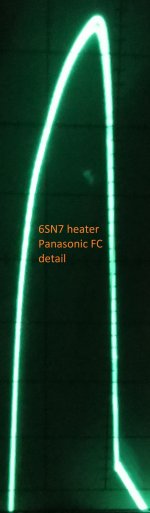
Panasonic FC is a low-impedance type, so it explains ringing. We may use this type on a second place of CLC (or CRC), but it can be better to avoid them totally. They are made for high-frequency DC/DC. It is better to use "usual impedance" type caps in low frequency rectifiers, I mean general purpose 85/105 C type.
You may add low-ESR type caps in parallel to general purpose type caps if you want - the later ones will slow down (absorb) the ringing of low-ESR ones.
Unitet ChemiCon had to resonate at least a bit too.
You may add low-ESR type caps in parallel to general purpose type caps if you want - the later ones will slow down (absorb) the ringing of low-ESR ones.
Unitet ChemiCon had to resonate at least a bit too.
Last edited:
I totally agree...but please look at the photos 🙂Panasonic FC is a low-impedance type, so it explains ringing. We may use this type on a second place of CLC (or CRC), but it can be better to avoid them totally. They are made for high-frequency DC/DC. It is better to use "usual impedance" type caps in low frequency rectifiers, I mean general purpose 85/105 C type.
You may add low-ESR type caps in parallel to general purpose type caps if you want - the later ones will slow down (absorb) the ringing of low-ESR ones.
Unitet ChemiCon had to resonate at least a bit too.
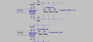
The 845 heater is only for the photo without the CMC and second C.
If you have any suggestions for the HV supply, please let me know.
Attachments
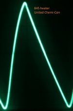
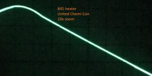
United Chemicon caps give a "normal" sawtooth-type of ripple (portion of sine and portion of a straight line). The picture is quite usual. A first rising part - sine - means charging of a cap through the open diodes from a transformer. A second (and last) part - straight line (almost straight line) - diodes are closed and a cap is discharging onto the load.
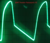
But Panasonic FC oscillogram is strange for me - I don't remember if I have seen ripple of such a type - with a gap between sine and straight parts (between charging and discharging).
But Panasonic FC oscillogram is strange for me - I don't remember if I have seen ripple of such a type - with a gap between sine and straight parts (between charging and discharging).
Last edited:
Ok. I am now a bit far from my programs to calculate rectifier and filters (I am on weekend) so I can say more in a day or two later. (I have only my smartphone in my hands).
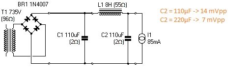
Now I see that HV load is about 10 kohm. 110 uF cap has to be ok for this load value (it has impedance about 15 Ohms (at 100 Hz). This is good because it is much lower then load resistance (10k). A 8 H inductor has impedance about 5 kohm, so it seems ok too, from first sight.
The last 'C' has impedance (15 Ohm) is much lower then 5k (of L) - this has to be good too.
Now I can only make short aproximate ripple values.
First 'C' cap has to have about 1.5 V ripple (can't say now RMS or amplitude, can't remember at the moment).
Then LC-part of a filter may have filtering coefficient about 300, so 1.5V/300 is 0.005 V or 5 mV ripple. It isn't much. This is inacurate calculation, but it still can give some info to think about. Anyway, if I'm not wrong, HV-ripple has to be somewere between 5-20 mV.
So, later I can say something more definite about HV ripple value, so we can compare it to OPT ripple value.
Rectification of HV-calculations:
With 900VDC and 82 mA load current you have about 1.9 V RMS of a riple voltage on the first cap of your CLC filter. It is about 5.7 V ripple amplitude.
Your LC filter has filtering coefficient of about 220. So you have an HV ripple about 1.9/220 = 9 mV RMS or 26 mV of a ripple amplitude.
And what is a ripple amplitude at the amp output?
Last edited:
I measured at the diode bridge +/- terminal, in front of the resistors to the caps. IMHO this is diode drop + resistor drop.United Chemicon caps give a "normal" sawtooth-type of ripple (portion of sine and portion of a straight line). The picture is quite usual. A first rising part - sine - means charging of a cap through the open diodes from a transformer. A second (and last) part - straight line (almost straight line) - diodes are closed and a cap is discharging onto the load.
But Panasonic FC oscillogram is strange for me - I don't remember if I have seen ripple of such a type - with a gap between sine and straight parts (between charging and discharging).
With Duncan PSUD2 I get 14 mVpp, if I double the last cap 7 mVpp.Rectification of HV-calculations:
With 900VDC and 82 mA load current you have about 1.9 V RMS of a riple voltage on the first cap of your CLC filter. It is about 5.7 V ripple amplitude.
Your LC filter has filtering coefficient of about 220. So you have an HV ripple about 1.9/220 = 9 mV RMS or 26 mV of a ripple amplitude.
About 8 mVpp, see photo in post #71.And what is a ripple amplitude at the amp output?
Attachments
It is standard for SE amp. Usually the driver stage is used to activly compensate for the ripple by injecting the right amount of ripple.Is it ok for your amp? Lamp amps may have low PSRR. Is it so for yours? If not then active filter may help (capacitance multyplier). Example is in an attachment (it is lower voltage one).
Gyrator comparison: https://www.diyaudio.com/forums/power-supplies/155657-mosfet-gyrator-using-irf840-3.html#post1996151
Another possibility is Higher-Voltage Feedforward-Shunt Regulator: High and Low Voltage Feedforward Shunt Regulators
Actual CLC filter seems ok, so I don't know what to recommend, except increasing C and L values or an active filter (gyrator etc).
O.k. I came to the same conclusion. Thank's again for helping !Actual CLC filter seems ok, so I don't know what to recommend, except increasing C and L values or an active filter (gyrator etc).
- Home
- Amplifiers
- Power Supplies
- Why gets the capacitor cooked ?