I found info about your PS:
- from the previous tests we know that ultrafast type may be not good with your transformer. We have to "slow down" them a little. There are at least three ways. 1) You can find something like BYV29 (soft recovery) but with higher voltage rating. 2) You may use BYV29-500 but three-four in series (four I think. It is costly). 3) You may add some series resistance to each existant UF5400 diode (something about 1 R, I ca't say exact value). This may made them more "soft". 4) Use usual rectifier diodes like 1N4007 - only two in series and very cheap! (And may work). Three in series may be safer (more reliable)."I agree on pt.5, please keep in mind there are three power supplies in action. One is the heater, two is the HV (UF5408 diodes, two in series, I can only measure up to 300V and this is 980 V) and three is the negative bias supply (UF4007 diodes) and looks more or less clean. The UF diodes are 'ultra fast, slow recovery' type."
Last edited:
There is nothing wrong with your circuit in post #32. None of the values are critical.
Use a single ended inductor.
Add two resistors after the diode bridge.
Add (large) film capacitors in parallel with the electrolytic capacitors.
Use a single ended inductor.
Add two resistors after the diode bridge.
Add (large) film capacitors in parallel with the electrolytic capacitors.
Actually there are eight secondaries, two are AC heaters, the others produce DC. There is HV, MV, negative bias, heater for 845, heater for small triodes and small 5 V DC for display 😀.I think the same parasitic ringing is present (has to be present) on all secondaries. And HV usually have the most short path to output (I mean has the lowest PSRR for this). So snubber on HV supply has to have the largest impact.
But if there are, for example, three secondary windings - you have to put snubbers at least at two of them.
If there are two secondaries - you may need either one snubber or two snubbers (on both second. W.).
Good to hear that you are o.k.Be careful with HV DC voltage. I was caught by 450 VDC once - it was one of the most dangerous moments in my life (I had some problem with my arm for about 2-3 years. Now it is ok).
What formula do you use to design the snubbers ?
Thank's again for helping !!!
It is in place since post #56.N101N said:Use a single ended inductor.
Sorry, this is not possible because of voltage drop.Add two resistors after the diode bridge.
Thanks for the suggestion, but that doesn't work at all in this circuit.Add (large) film capacitors in parallel with the electrolytic capacitors.
The BYV29-500 are a lot better than the KBPC3510, but still benefit from the snubber. HV snubber is necessary as well. Thank You Vovk Z
Attachments
-
 CMC2.jpg124.2 KB · Views: 129
 -
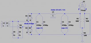
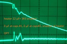
 HV 100 nF+99R, heater 22 µF+3R3, OPT.jpg540.1 KB · Views: 63
 -
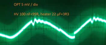
 HV 100 nF+99R, heater 22 µF+3R3, Zoom 10x.jpg361 KB · Views: 58
 -
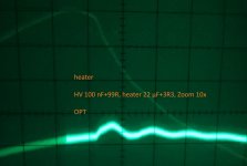
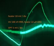 HV 100 nF+99R, heater 22 µF+3R3.jpg754.9 KB · Views: 62
 -
 0 µF at caps #1, 0 µF at caps#2, snubber at heater.jpg600.2 KB · Views: 61
 -
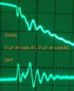 0 µF at caps #1, 0 µF at caps#2.jpg447.7 KB · Views: 111
 -
 0 µF at caps #1, 22 µF at caps#2.jpg494.6 KB · Views: 108
 -
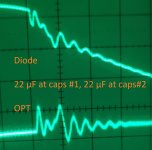 22 µF at caps #1, 22 µF at caps#2.jpg437.3 KB · Views: 118
 -
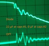 22 µF at caps #1, 0 µF at caps #2.jpg440.8 KB · Views: 115
Snubbers have to be on the powerful ones, so on most of them.Actually there are eight secondaries, two are AC heaters, the others produce DC. There is HV, MV, negative bias, heater for 845, heater for small triodes and small 5 V DC for display 😀.
There are strict theories and more or less accurate formulas. But I use my fast approximation derived from experience and theory. It is for low-frequency transformers only.What formula do you use to design the snubbers ?
To start you have to know only several values: secondary winding DC resistance (it is about 5% from this secondary rated load resistance), load resistance, and secondary voltage value. Knowing those values it is easy to get RC-snubber resistor value: it is somewhere in between of those three. (One volt of a secondary means one ohm of the resistor). For example, we have a secondary winding with 500 VAC, 0.25 A rated and an actual load let be 1000 Ohm.
That means this secondary winding has about 50-100 Ohms DC resistance (you can measure yours and take your number). Let it be 100 Ohm.
So we have such numbers: 100 Ohm, 500 Ohm (from 500 VAC), and 1000 Ohm. Having these numbers I see that optimum resistor value (or a starting point to choose) can be somewhere in between 100 ... 1000 Ohm.
Let it be 510 Ohm.
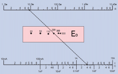
Next step we need a capacitor value. We have to know a parasitic ringing frequency. If we don't know - let it be 100 kHz for a large transformer (like yours), and for example, 500 kHz for a small transformer (less then 10-20 VA). It can be lower than 100 kHz too. Those numbers are very inaccurate, but snubber calculations have not to be accurate. You have an oscilloscope so you may get your ringing frequency from your pictures. In our example, it is 100 kHz. RC-snubber f(-3dB) frequency has to be at least two times (or more) lower than ringing frequency. Let it be f = 20 kHz. Then C is 1 / (2*pi*R*f) = 0.016 uF (or larger).
So, we may use 0.015 uF, 0.022 uF, 0.033 uF, 0.047 uF (we may try 0.01 uF and 0.1 uF too).
That's it.
We may use a graphical nomogram for arc-suppression RC-circuit too, it gives similar values without calculations, graphically (but a bit higher in frequency). An example is in the attachment.
Attachments
Last edited:
Looking at your last pics, we can definitely see that HV-snubber works. The picture is not ideal, maybe, because of a lack of snubbers on all ringing secondaries (they induct parasitic ringing signal onto each other).
To make a picture closer to an ideal we have to do that in an iterative way - do this for all secondaries (for first approximate iteration). Then we may relax, or start a second (or a next), the same iteration - try to change R and C snubber values on all windings and see if it became better or not.
I think you may now decrease the 22 uF cap in your heater winding to 2.2 uF, or even to 1 uF (with HV-snubber present, of cause).
Last edited:
Sorry for the long note but people seem to misunderstand transformer snubbing.
Please note that it is the resistor that dampens the oscillation. The oscillation is caused by the secondary inductance continuing to "push" current after the rectifier diode reverse biases to non-conducting and that current charging the transformer parasitic capacitances - forming a tuned circuit which then oscillates. Sometimes at 100's of megahertz but always in little bursts at the mains frequency. Hence it sounds like mains hum.
The resistor must be small enough dissipate the stored energy in the inductance. I use 100 ohms as a matter of convenience because it almost always over-damps the oscillation (which is good). Under-damped is bad and critically damped is that silly magic line between effective and not - why bother?
The series capacitor needs to be a short circuit for the oscillation frequency and high impedance for the mains frequency. I aim at around 2k ohms (90mW at 30mA) or 1u5 for the 50 Hz where I am.
The shunt capacitor has the task of reducing the parasitic oscillation to a reasonable frequency from what may be a very high frequency. I use 470nF. High frequencies radiate lots of energy at small wire lengths so you do not want this. Radiated energy is the stuff causing the hum. Because of this the snubber components MUST be mounted as close as possible to the transformer. Mounting them at the rectifier is pointless.
Finally all transformer secondaries must be snubbed and I choose to be lazy and apply identical snubbers across all. For high voltage secondaries power and voltage ratings need to be observed of course.
Hope this helps.
Thanks a lot again !There are strict theories and more or less accurate formulas. But I use my fast approximation derived from experience and theory. It is for low-frequency transformers only.
To start you have to know only several values: secondary winding DC resistance (it is about 5% from this secondary rated load resistance), load resistance, and secondary voltage value. Knowing those values it is easy to get RC-snubber resistor value: it is somewhere in between of those three. (One volt of a secondary means one ohm of the resistor).
The HV has DC resistance 97 Ohm, 700 V AC and the actual load would be 1k - 2k. Another beginner question, how do I calculate or measure the actual load if it is not a simple resistor ?
The MV has DC resistance 48 Ohm, 250 V AC and the heaters maybe 100 mOhm (more guessing than measuring).
I will try to make snubbers for the individual secondaries, i.e. only one heater first then second heater and so on and combine them later.To make a picture closer to an ideal we have to do that in an iterative way - do this for all secondaries (for first approximate iteration). Then we may relax, or start a second (or a next), the same iteration - try to change R and C snubber values on all windings and see if it became better or not.
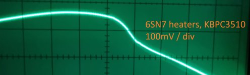
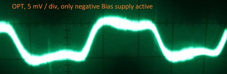
The 6SN7 heater supply, using KBPC3510, drawing 1.2 A looks clean without snubber (nothing else active).
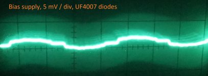
The negative Bias supply, which draws some mA and uses UF4007 diodes looks 'good enough' I guess (nothing else active). Although there is almost no load from the negative Bias supply the OPT has already the ripple. OPT and xfmr have the same orientation.
Yes, that worked.I think you may now decrease the 22 uF cap in your heater winding to 2.2 uF, or even to 1 uF (with HV-snubber present, of cause).
Attachments

Thank you for your long and informative posting. If you would have written 'use 100 ohms + 1u5 and 470nF' I would have learned nothing, please keep writing long notes.Sorry for the long note but people seem to misunderstand transformer snubbing.
For example, put 1 Ohm resistor in series and measure a voltage drop across it. But I think you have to know it approximately.Another beginner question, how do I calculate or measure the actual load if it is not a simple resistor ?
Similar windings need the same snubbers. I think it is your time to get your own experience so it is better if you do it as you want (in your way) and see with your own eyes. I can only add that with an only one snubber but many loaded unsnubbered windings it is hard to see something. It has to be easier to add snubbers incrementally. I mean, fir example, if you found HV snubber - don't remove it. Find next one for next winding (MW secondary, for example).I will try to make snubbers for the individual secondaries, i.e. only one heater first then second heater and so on and combine them later.
But this is my experience - it is better if you get your own.
Last edited:
Sorry I should have written more explicit:I can only add that with an only one snubber but many loaded unsnubbered windings...
"I will try to make snubbers for the individual secondaries, i.e. only one secondary active, the other secondaries without load. For example only one heater first, then only second heater and so on and combine them later. This should be faster than trying all of them the same time from the beginning."
This way I guess I could get correct snubber values for the two heater secondaries, the negative bias supply and the MV. The 5V supply will be ignored. I should be able now to get a correct HV snubber, as the heater snubber is already in place (I cannot check HV without 845 heater).
The other possibility would be to use an external supply for the 845 (and hope that the negative bias can be ignored), make the HV snubber and then the 845 heater snubber and then the other secondaries.
Thanks again for helping !!!
After the test with the big foil cap parallel to the 2x 4700µF I ordered new caps with 6800µF. These do not resonate at all and I use the CMC again. Those caps made a big difference.
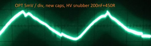
Testing one and only one active secondary it became clear that the heaters are fine and the main culprit is the HV. I tried Cs=100-200nF and Rs=99R-2040R and got the best result with Cs = 200nF and Rs = 450R (3x 150R for voltage rating).
The old 100nF+99R didn't work any longer (resonance) and Cx=10nF wants to resonate as well.
Attachments
Fine!
One problem is gone.
Now there is a problem with a low PSRR of the amp (because this last screen looks totally similar to rectified and filtered DC voltage from power supply (only smaller proportionally).
One problem is gone.
Now there is a problem with a low PSRR of the amp (because this last screen looks totally similar to rectified and filtered DC voltage from power supply (only smaller proportionally).
Last edited:
The HV is a CLC supply and there is no room for CLCLC. Maybe I have to use a feed forward shunt regulator, but space is limited in this chassis.Now there is a problem with a low PSRR of the amp (because this last screen looks totally similar to rectified and filtered DC voltage from power supply (only smaller proportionally).
The other problem is the arrangement of the transformers. They should be 90° to each other, but the power transformer has the same orientation as the OPT, the choke is turned 90°. The picture shows the induced ripple. A flux band would help, but I don't know how good the isolation is on these Chinese transformers.
I don't know what to do...
Attachments
Previous picture, with sawtooth-like ripple definitely looks like power supply ripple, but not transformer coupled.
Maybe, you may optimize actual CLC? What is a HV load current value, (approximately), and what CLC do you use?
Maybe, you may optimize actual CLC? What is a HV load current value, (approximately), and what CLC do you use?
Totally agree.Previous picture, with sawtooth-like ripple definitely looks like power supply ripple, but not transformer coupled.
Some things happening here that I don't understand. My DMM tells me about 0.2 mVrms on the secondary of the OPT with no power applied. Switching the amp on only with the negative bias active (draws some mA), but no HV, no MV, no heaters,...I get 5.7 mVrms. The transformers have the same orientation, turned the PT 90° and got 5.1 mVrms, should be less according to the theory. Added a flux band, basically no change at all, should get smaller values according to the theory (maybe internal screen ?).
The class A bias is about 85 mA.Maybe, you may optimize actual CLC? What is a HV load current value, (approximately), and what CLC do you use?
The caps (220µF / 500 V) are on top of each other (110 µF) to get the 1 kV rating and have 220 kOhm in parallel. The choke is in the HV leg and has 8H and 55 Ohm.
You wouldn't happen to have a 4 foot fluorescent fixture lighting your work area, by any chance?
Your waveform in post #73 sure reminds me of some EMI from an old ballast I had once.
One thing pretty sure -- it's too far from a sawtooth to be the usual conduction mechanisms.
And also pretty sure you didn't follow the earlier poster's suggestion to study Mark Johnson's Quasi/Cheapomodo threads. You can do all of this snubber testing/verifying at perfectly safe voltages, regardless of their normal operating potentials.😉
One other point you might have missed in those long-ish threads: A great many 1k, 2k, and 5k trimpots don't *trim* all the way down to 10 ohms and below, which low voltage high-current secondaries often require.
Regards
Last edited:
No external source. As stated "My DMM tells me about 0.2 mVrms on the secondary of the OPT with no power applied.....5.7 mVrms powered."You wouldn't happen to have a 4 foot fluorescent fixture lighting your work area, by any chance?
The post #73 photo shows the "transformers only" waveform, no tubes active.Your waveform in post #73 sure reminds me of some EMI from an old ballast I had once.
One thing pretty sure -- it's too far from a sawtooth to be the usual conduction mechanisms.
The post #71 photo shows the working amp photo and this is the sawtooth Vovk Z is mentioning.
According to my DMM the lowest setting of the used 2k trimpot is 2.08 Ohm.One other point you might have missed in those long-ish threads: A great many 1k, 2k, and 5k trimpots don't *trim* all the way down to 10 ohms and below, which low voltage high-current secondaries often require.
I was reading parts of the Mark Johnson's Quasi/Cheapomodo threads as well as his Linear Audio article, the Morgan Jones article and lots of other stuff from "famous gurus" before I opened this thread. I have tried the guru values and they simply didn't work for me as and why can be seen in the previous posts. NO, I do not say Mark Johnson is wrong !!! Actually the latest working value is close to his recommendations (only the recommended Cx didn't work at all in THIS case).And also pretty sure you didn't follow the earlier poster's suggestion to study Mark Johnson's Quasi/Cheapomodo threads. You can do all of this snubber testing/verifying at perfectly safe voltages, regardless of their normal operating potentials.
The Vovk Z approach made sense to me and worked as demonstrated in the past posts !!!
Ok. I am now a bit far from my programs to calculate rectifier and filters (I am on weekend) so I can say more in a day or two later. (I have only my smartphone in my hands).The class A bias is about 85 mA.
The caps (220µF / 500 V) are on top of each other (110 µF) to get the 1 kV rating and have 220 kOhm in parallel. The choke is in the HV leg and has 8H and 55 Ohm.
Now I see that HV load is about 10 kohm. 110 uF cap has to be ok for this load value (it has impedance about 15 Ohms (at 100 Hz). This is good because it is much lower then load resistance (10k). A 8 H inductor has impedance about 5 kohm, so it seems ok too, from first sight.
The last 'C' has impedance (15 Ohm) is much lower then 5k (of L) - this has to be good too.
Now I can only make short aproximate ripple values.
First 'C' cap has to have about 1.5 V ripple (can't say now RMS or amplitude, can't remember at the moment).
Then LC-part of a filter may have filtering coefficient about 300, so 1.5V/300 is 0.005 V or 5 mV ripple. It isn't much. This is inacurate calculation, but it still can give some info to think about. Anyway, if I'm not wrong, HV-ripple has to be somewere between 5-20 mV.
So, later I can say something more definite about HV ripple value, so we can compare it to OPT ripple value.
Last edited:
I wanted to ask what a type were old caps and what are the new ones? (It is interesting behaviour).After the test with the big foil cap parallel to the 2x 4700µF I ordered new caps with 6800µF. These do not resonate at all and I use the CMC again. Those caps made a big difference.
Last edited:
The problematic ones are Panasonic FC 4700 µF 25 V:I wanted to ask what a type were old caps and what are the new ones? (It is interesting behaviour).Quote:
Originally Posted by alujoe2 View Post
After the test with the big foil cap parallel to the 2x 4700µF I ordered new caps with 6800µF. These do not resonate at all and I use the CMC again. Those caps made a big difference.
EEUFC1E472 - Aluminum Electrolytic Capacitors (Radial Lead Type) - Aluminum Electrolytic Capacitors - Industrial Devices & Solutions
I replaced them in the front with: United Chemi-Con 6800 µF 25 V
http://www.chemi-con.co.jp/cgi-bin/CAT_DB/SEARCH/cat_db_al.cgi?e=e&j=p&pdfname=kyb
As you might remember the original cap was a 15mF, I didn't have replacement parts and used 2x 4m7.
In the meantime I tried some other caps as well (2x 4m7, 1x 10mF and 1x 15mF) and those worked as well.
In the diode bridge - C1 - CMC - C2 arrangement the worst result was C1 = 2x FC and C2 = 2x FC, but even with C1 = 2x 6m8 and C2 = 2x FC there was resonance (but much less).
My best guessing in the moment is that this CMC and the FCs are perfectly tuned for resonance. I believe that C1 and C2 should not be the same caps, maybe best with C1 = 10mF and C2 = 22mF.
- Home
- Amplifiers
- Power Supplies
- Why gets the capacitor cooked ?