I've just double checked my layout diagram and I did connect the circuit as you have shown.
One thing I have realised though is that the ground rail for that part of the circuit may in fact be isolated from the chassis ground - I reused the original input jack which is an insulated type.
As it is an audio input, should that ground be hooked up to the chassis ground via a 10 ohm resistor + 100nf + anti-parallel diode hum breaker set up or should it just be connected straight to chassis?
This made my week: (Thank you, Tube Lab!!)😀
One day while blasting the classroom with some 60's rock I made 3 simultaneous discoveries.
1) Stromberg had used pin 1 on one of the 4 6L6GB sockets as a tie point for the screen dropping resistor, pitting a couple hundred volts on the tube's shell.
2) The foil album cover on Stepenwolf's second album conducts electricity.
3) It flies like a Frisbee when the dumb blonde one accidentally touches it to a metal 6L6 while leaning against a grounded metal bench in the classroom.
You are using an old tube. Filament continuity does not mean tube can work. You can use analog multi meter like sanwa in the x10k range to check if tube is working (conducting). The multi meter in this range uses 9v for resistance check. Disconnect all voltages other than the filament. Apply filament power. The dc resistance with grid to cathode would be around 200 ohms, cathode to anode would be around 20k ohms. suppressor and screen readings will be in between. (will read only one way like a diode, other way will be infinity) It is common for the dry solder at the pins. Regards,
Not sure if you wired per the scheme or this corrected version per the red line.
That's the old fashioned way to do it... on more modern schematics, lines crossing at right angles = no connection. Lines crossing at right angles, with a dot placed on top of the junction = connection. It's clear that's the convention this schematic follows.
https://www.americanradiohistory.com/Archive-Radio-Electronics/40s/Radio-Electronics-1949-05.pdf
page 78 bottom Audio Equalizer
page 78 bottom Audio Equalizer
Thank you. You made me remind of my Simpson 260 multi meter, served me for very long.
According to your posting #7, you measure 270 V at the anode but 0V between anode and cathode. This means, the cathode is floating and has no connection to the negative supply rail via the 2.7 k resistor. In this case, grid 2 will also measure 270 V
Thanks aboos.
I realised that the input jack (that shows as being the source of ground on the schematic) is the insulated type.
When I get home, I'll put a proper ground line in and fire it up again. It should work then, and I'll report back how it goes.
I realised that the input jack (that shows as being the source of ground on the schematic) is the insulated type.
When I get home, I'll put a proper ground line in and fire it up again. It should work then, and I'll report back how it goes.
Ok so the culprit was a bad connection downstream of the heater chain.
The tube seems to be running on the cold side if I am using the Robinette Tube Bias Calculator correctly.. (probably not!).
Anode (Pin 8) to Cathode (Pin 5) = 91.3v
Gnd to Grid (Pin 6) = 70.5v
Gnd to Cathode Resistor (2.7k/Pin 5) = 3.1v
The calculator seems to suggest plate current is 1mA, which gives dissipation at 12.1%.
Do these voltages make sense?
Ok so the culprit was a bad connection downstream of the heater chain.
You put all efforts to test. Best of luck.
... dissipation at 12.1%....
So? This is NOT a Power Amp. Oh, all amplifiers have to make Power, but the signal power here is so incredibly small (microWatts) that there is no reason to run the tube HOT.
Anyway you know the current is less than 1mA--- 270V supply and 270V plate resistor. If the tube were a dead short, it would pass 1mA of DC (and zero signal). More likely the plate should sit 1/3rd-2/3rd of supply so 0.3ma to 0.7mA. Sure, less than 1/10th Watt Pdiss. They don't make tenth-Watt tubes so we use a Whole Watt tube and work it easy.
Why low current? Cost of B+ filtering in this very low-level stage. And Gain: voltage gain of tubes and FET rises as current falls. Gm does not fall as fast as current.
Attachments
Last edited:
Thanks for taking the time to explain.
I wasn't thinking that every tube needs to be 'cranked up to 11', but I was concerned because the current and voltages were way down the bottom of the datasheet graphs and did not look right. I was expecting dissipation to be something like 50-60%, in the more linear area of the graphs.
But it makes sense, as you explain, with such small signals.
For this version, D is 330V so top current is 1.2mA, and 0.33mA at the 1 Meg.
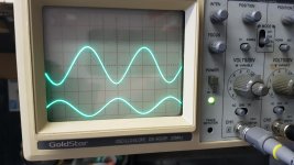
I'm just waiting on some 6V6S tubes now, as the plates are set at 425v which is way too high for the 6P6S that I have on hand. Then I'll see if I'm getting a nice sine wave.. 🙂
I wasn't thinking that every tube needs to be 'cranked up to 11', but I was concerned because the current and voltages were way down the bottom of the datasheet graphs and did not look right. I was expecting dissipation to be something like 50-60%, in the more linear area of the graphs.
But it makes sense, as you explain, with such small signals.
For this version, D is 330V so top current is 1.2mA, and 0.33mA at the 1 Meg.
I'm just waiting on some 6V6S tubes now, as the plates are set at 425v which is way too high for the 6P6S that I have on hand. Then I'll see if I'm getting a nice sine wave.. 🙂
> the more linear area of the graphs.
Linearity is all relative.
Plotted to 10mA max, yes a half-mA looks scrunched.
Plot just the range to 1mA. Now the linearity is the same around 0.5mA as it was around 5mA on the 10mA graph.
Large changes should be plotted on log graph. (Somehow this was rarely done, though the MIT Radar books do.) Now the low end looks like the high end, maybe better. Plot the 3/2 power of voltage and the graphs get straight. It's all relative.
Anyway how much linearity does a film projector need? (The nonlinearity of optic film is horrible.) Especially at this part-Volt level?
Anyway how much linearity does a film projector need? (The nonlinearity of optic film is horrible.) Especially at this part-Volt level?
This one is a conversion of a 1940's projector amp into a guitar amp. The optical tube is gone as are the old defective bits that would likely catch fire if I were to power up.
I guess the same question applies... How much linearity is required for a guitar amp.....
Thanks for the pointers with the data sheets. I'm not used to deciphering the tube data sheets, so this is also a learning project for me.
Looks to be working pretty nicely now 🙂
Attachments
That's the old fashioned way to do it... on more modern schematics, lines crossing at right angles = no connection. Lines crossing at right angles, with a dot placed on top of the junction = connection. It's clear that's the convention this schematic follows.
Yes but there are missing dots in many places, so confusion is possible.
I'm just waiting on some 6V6S tubes now, as the plates are set at 425v which is way too high for the 6P6S that I have on hand.
I've run them that high...Hell, I've put them in place of 6P3S "just to see" and while they got HOT, they worked fine. I didn't run them that hot (20W Pd) for long though.
- Status
- Not open for further replies.
- Home
- Amplifiers
- Tubes / Valves
- Why doesn't this 6SJ7 work?