Class AB is often touted as having a higher efficiency than Class A (which is true), but it often overlooked that Class AB distortion characteristics are essentially the same as Class B (i.e. really bad). Here is an example:
You decide to build a super-duper 300B amplifier, and settle on a push-pull output stage. You know a single 300B is happy to drive 3k load, so for push-pull you get 6k:8 output transformer. You decide to save a little bit on power, and run the stage at 30mA idle current per tube. It's Class AB (Class A would idle at 70-80mA), so you should get 15W power output no problem, right?
Wrong. Here is what happens instead:
Attachments
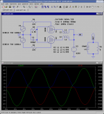
Distortion at 7W output is about 10%, and the waveform looks really bad. In comparison, if I was running the tubes in Class A at 60mA idle current per tube, I would get my 15W at 0.5% THD.
The moral is that for a given tube, Class AB operation is not going to give me more output power than Class A at a given distortion level (say, 5%). Of course, if I use feedback, I can make Class AB stage respectably linear, but I can do the same to Class A, so there is no real advantage to using AB...
The moral is that for a given tube, Class AB operation is not going to give me more output power than Class A at a given distortion level (say, 5%). Of course, if I use feedback, I can make Class AB stage respectably linear, but I can do the same to Class A, so there is no real advantage to using AB...
That is why negative feedback is necessary in a class AB amp. I would imagine a small amount of negative feedback would fully clear up this crossover distortion in the schematic pictured.
If anyone was making a PP amp with no feedback they would be well advised to make it operate fully in class A, even if it shortens the life of the output tubes.
If anyone was making a PP amp with no feedback they would be well advised to make it operate fully in class A, even if it shortens the life of the output tubes.
Another often overlooked item is the P-P load difference in class-ABx. Two steps to fixing the problem, 1) Add NFB and 2) increase the P-P load 🙂
That's odd, I've had plenty of p-p amps around here with no loop feedback, and the distortion is no higher than SE, in fact, often much lower. For example, in an amp in front of me at the moment, a pair of 7027A in AB1 triode, 8K plate-to-plate give me 10 watts at under 1% THD before feedback. 1W distortion is under 0.05%, totally dominated by third.
So, if what you're saying is that one can come up with a hack circuit that doesn't work well, OK, that's true. But if you're trying to claim any universality to that observation, I'm sorry, it's just not correct.
edit: to do your comparison properly, you need to recognize that keeping the load constant requires the plate to plate load to be 4x higher than a single tube.
Hi Gregg,
Yeah, and because of this the spice simulation done by Andrei proves nothing at all. Or since when does spice adjust the load conditions from Raa/2 to Raa/4 (as seen by a single tube in a PP pair) automagically and smoothly, when doing the slow transition from class A1 to B1?
Damn simulations 😉
Tom
Geek said:Another often overlooked item is the P-P load difference in class-ABx.
Yeah, and because of this the spice simulation done by Andrei proves nothing at all. Or since when does spice adjust the load conditions from Raa/2 to Raa/4 (as seen by a single tube in a PP pair) automagically and smoothly, when doing the slow transition from class A1 to B1?
Damn simulations 😉
Tom
Hi,
I am assuming that the distortion figures comes from a simulator? If so then the result would be very dependant on how good the model is.
Even so the result is not that surprising for a tube like 300B and is well known. In this paper http://www.clarisonus.com/Archives/TubeTheory/BeamPower.pdf
on pages 38 and forward this phenomena is described for theoretical triodes and also make a comparison with beam power tubes showing that these can give lower distortion in AB than triodes.
I think it is important to note that distortion level in AB with real triodes depend on the triode curve itself, and the chosen operating point.
Please also read what is written in the paper about the 0 distortion class B1 operation point that gives lower distortion than AB.
In some other books like Terman it is described about using projected cutoff operating point for tubes operating in close to B, the theory here is that there is a operating point for some triodes which give a minimum of distortion, this is usually at very low idle current.
So in contradiction to what many believe at least for triodes lower idle current and operating close to class B can give better results than operation closer to A.
Some regulator triodes like 6AS7 and 6C33C have more remote cutoff than e.g 300B, and they operate with a clear distortion minima at a quite low idle current in class AB.
Regards Hans
Hi Tom,
I have found simulations only useful for finding DC operating points and quite useless for analog AC parameters 😉
I have found simulations only useful for finding DC operating points and quite useless for analog AC parameters 😉
tubetvr said:on pages 38 and forward this phenomena is described for theoretical triodes and also make a comparison with beam power tubes showing that these can give lower distortion in AB than triodes.
Yes, theoretically they can, but the ideal load range is very small. For many well known tetrodes/pentodes the manufacturers do supply distortion nomograms in the spec sheets. You can see there, that the least distortion point is very distinguished and distortion rises steep sideways from that ideal load point.
In real world circuit with real world loads (like speakers changing their impedance over frequency - thus giving a reflected load to the tubes with an error multiplied by OPT impedance ratio!) that means, that triodes usually are much more forgiving to load mismatching by real world loads like speakers.
Tom
The impedance ratio in an OPT is the square of the turns ratio. To present each tube with a 3K ohm load you need a 12K P-P transformer.
At least that is what the theory says. My amplifier (P-P 300B) runs a 6.6 K transformer that was made for 6L6's. I set the bias at about 45 mA per tube which allows class A operation up to about 10 Watts, at that point the amp crosses into AB1. I get 26 to 28 watts per channel from this amp. It has no local or global feedback. There is no visible crossover distortion, and the measured performence is quite good also.
At least that is what the theory says. My amplifier (P-P 300B) runs a 6.6 K transformer that was made for 6L6's. I set the bias at about 45 mA per tube which allows class A operation up to about 10 Watts, at that point the amp crosses into AB1. I get 26 to 28 watts per channel from this amp. It has no local or global feedback. There is no visible crossover distortion, and the measured performence is quite good also.
Geek said:Hi Tom,
I have found simulations only useful for finding DC operating points and quite useless for analog AC parameters 😉
Yeah !
It's very difficuly to fully "switch off" a "real" 300B !
At very hi anode voltages where this should occur, expect a huge negative grid voltage swing to remove the least milliamp !
Yves.
Some of you are no doubt familiar with the 300B PP amplifier I designed for an article in VTV about 7 years ago, that amplifier normally runs class A at 70-80mA per tube and will produce 25Wrms out at <1%, 30W @ 2% thd no feedback, reduce the plate current to about 40mA per tube and the distortion increases to less than 2% at 25W.
Note that at power levels of 10W and below I was not able to measure any significant difference at all. This design used fixed bias incidentally which makes it very simple to do these sorts of experiments.
Plate to plate impedance of the output transformer used is 3.8K and VP is 400V.
The article on this design is now available on my site if you are interested.
P-P load difference in class-ABx is indeed often overlooked. Especially the fact that the load seen by the tube changes depending on wether the other tube is conducting or not. If the other tube is in cut-off, the load is 1/4 of primary, while if the other tube is conducting, it's 1/2 of primary impedance.
Since always. Transformers are correctly modelled as coupled inductors in Spice, dynamical effects and all. (n1/n2)^2 impedance reflection formula is a simplification.
Simulation of course is not exact, and depends on the quality of the models used (the ones I used are fairly accurate and are made from Sophia-traced 300B data), but it illustrates the problems you might have. So no, I do not believe THD number of Class AB, but yes, I am pretty sure it will be higher than in Class A if I prototype.
The example I chose is intentionally extreme to make a point, but is not that atypical (nor is it a hack circuit). You can do various things to improve Class AB, like play with the load or use a remote cutoff triode. But IMO, it is better to simply run it in Class A, unless there are special reasons that prevent you from doing so. And BTW, I don't buy "the feedback will take care of it" argument, as the same feedback loop will make Class A stage more linear still.
It is. But AB amplifiers still abound and have their proponents, as this thread is the evidence of 🙂.
Since when does spice adjust the load conditions from Raa/2 to Raa/4 (as seen by a single tube in a PP pair) automagically and smoothly, when doing the slow transition from class A1 to B1?
Since always. Transformers are correctly modelled as coupled inductors in Spice, dynamical effects and all. (n1/n2)^2 impedance reflection formula is a simplification.
I am assuming that the distortion figures comes from a simulator? If so then the result would be very dependant on how good the model is.
Simulation of course is not exact, and depends on the quality of the models used (the ones I used are fairly accurate and are made from Sophia-traced 300B data), but it illustrates the problems you might have. So no, I do not believe THD number of Class AB, but yes, I am pretty sure it will be higher than in Class A if I prototype.
The example I chose is intentionally extreme to make a point, but is not that atypical (nor is it a hack circuit). You can do various things to improve Class AB, like play with the load or use a remote cutoff triode. But IMO, it is better to simply run it in Class A, unless there are special reasons that prevent you from doing so. And BTW, I don't buy "the feedback will take care of it" argument, as the same feedback loop will make Class A stage more linear still.
Even so the result is not that surprising for a tube like 300B and is well known.
It is. But AB amplifiers still abound and have their proponents, as this thread is the evidence of 🙂.
Hi Yves,
Indeed!
At high Va, it is likely we'd get a nasty g-k or g-a arc in the tube before we cutoff the last mA in real life
Yvesm said:
It's very difficuly to fully "switch off" a "real" 300B !
At very hi anode voltages where this should occur, expect a huge negative grid voltage swing to remove the least milliamp !
Indeed!
At high Va, it is likely we'd get a nasty g-k or g-a arc in the tube before we cutoff the last mA in real life
Some new production 300B's have some filament wire exposed above the grid wires. This creates a path for current to flow directly from the filament to plate. Even though the path is small and long, if the plate voltage is high enough no amount of negative grid voltage can cut the tube off.
I have seen this on some Sovteks at voltages over 400 volts.
I have seen this on some Sovteks at voltages over 400 volts.
andrei said:Class AB is often touted as having a higher efficiency than Class A (which is true), but it often overlooked that Class AB distortion characteristics are essentially the same as Class B (i.e. really bad). Here is an example:
You decide to build a super-duper 300B amplifier, and settle on a push-pull output stage. You know a single 300B is happy to drive 3k load, so for push-pull you get 6k:8 output transformer. You decide to save a little bit on power, and run the stage at 30mA idle current per tube. It's Class AB (Class A would idle at 70-80mA), so you should get 15W power output no problem, right?
Wrong. Here is what happens instead:
"You decide to build a super-duper 300B amplifier, and settle on a push-pull output stage. You know a single 300B is happy to drive 3k load, so for push-pull you get 6k:8 output transformer."
That's not right. Give it the appropriate load and see what happens. Secondly, take a second LQQK at the results. That cross over ain't all that bad, as compared to what you routinely see with transistors. Add some NFB and it won't be that bad at all. Select a proper op-point for the 300Bs and it'll probably be pretty good.
There's no real reason to say "No" to AB2 in every single case.
 Like anything else, it all depends...
Something else to be aware of in LTspice, the transformer K coupling coefficient does not always work as expected, in very recent earlier releases it did not work at all for most typical audio transformer models, this has been recently fixed. Setting K to anything other than 1 with large inductors may result in erratic convergence behavior and inaccurate results - if you are attempting to model leakage inductance it is a lot safer to just add the leakage terms as small external (to K) inductors, this incidentally is also true of the dcr.
Note that 300B models (and other tubes) captured using Andrei's curve capture program do not model the non-linearity accurately near cutoff. (Capture is only 2 points on the curve.) There may be a few better models out there, I use a mix models and many of Duncan Monroe's are reasonably accurate even at the extremes. 3F4 models will work in LTspice without problems.
With good models I do get reasonably good correlation between simulated results and what I actually measure. Just changing tube brands sometimes has a significant effect on the measured linearity.
I don't think you can make such generalizations....
Each tube, each topology, Plate voltage used, Screen voltage used..ect.ect...the selected plate loading all play a role in the outcome of the amp and not really comparable...
For example the Macintosh circuit breaks the rules about breaking into AB without the cross-over notch...since the Class A drivers/ followers also drive the cathode/plate windings..they keep the OPT's small amount of leakage from seeing any cut-off of audio signal current...
You can get acurate simulations...the simulator is only as good as the model you put in there and if you rely on the crappy models that currently exist, then your wasting your time... Write your own models but don't use the standard equations...
Chris
Note that 300B models (and other tubes) captured using Andrei's curve capture program do not model the non-linearity accurately near cutoff. (Capture is only 2 points on the curve.)
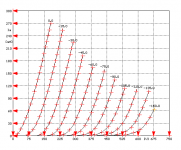
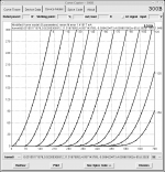
That is false. Here is the 300B curve tracer capture:
Attachments
- Status
- Not open for further replies.
- Home
- Amplifiers
- Tubes / Valves
- Why Class AB is bad