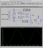
As you can see, the cutoff is modelled correctly (and it is easy to do for 300B, which is a hard-cutoff tube). The average model error is ~1.4mA.
OK, so if you can't blame the model, then it really IS a poorly designed circuit. Try modelling again, but with a 4x increase in plate to plate load compared to SE, and with the idle current chosen to minimize distortion instead of maximize it. Then your simulation might give you something closer to how competently designed real-world push-pull AB amps measure.
Leaving SY's implications of my competence aside, the answer to his question is this: with 12KCT:8 load and the same bias as in original example you obviously get less distortion - about 6.5% at 12W in Class AB2 - but much more than what is achievable in Class A. More instructive is the answer to the second suggestion - vary the idle current to minimize the distortion. Distortion is more or less monotonic function of idle current, with distortion figure always best at largest available idle current - i.e. optimizing Class AB stage for distortion you are driven to Class A operation. There is no "sweet spot" in idle bias. This has been generally true for all triode push-pull stages I've modelled so far.
A couple of questions:
1. What's the B+?
2. Why is the source impedance of the driver set at 27k?
1. What's the B+?
2. Why is the source impedance of the driver set at 27k?
425V.SY said:1. What's the B+?
No particular reason. A convenient value to represent grid-stopper resistor + previous stage impedance. It is irrelevant for the point I'm trying to make, as the grid current draw is not modelled, and Miller capacitance is too small to cause trouble at 100Hz. If I were designing a Class A2 stage, then I would worry about it 🙂.2. Why is the source impedance of the driver set at 27k?
Thanks. In a real AB2 amp, you'd want a source impedance well lower than that.
If, for this tube and this model, your sim shows distortion decreasing monotonically with increasing idle current, you should set that at something more like 85mA. Why use a 40W tube and not run it at 40W? I'd be curious to see what your model predicts under those conditions.
I haven't used 300Bs in p-p AB (there are better tubes for this application), but in one published circuit I have at hand (C. Schafer, "30 Watt High Fidelity Audio Amplifier" Audio Engineering, July 1947), with a 425V B+, 80mA idle, 4000 ohms plate-to-plate load, the measured distortion of the entire amp (no loop feedback!) was under 2% IMD (40Hz/12kHz) below 22 watts. Not too terrible, but I'll bet some playing with load lines could come up with something better.
At 425V B+ and running at 85mA idle per tube into 4kCT:8 load, the stage models really well. You get 15W out at 0.1% distortion. I would not believe that number too much, but distortion is definitely low. (In the real amp, some second order distortion will creep in from the tube mismatch.) Getting comparable distortion from a driver is going to be tough...
That's what I've been trying to say 🙂.
If, for this tube and this model, your sim shows distortion decreasing monotonically with increasing idle current, you should set that at something more like 85mA. Why use a 40W tube and not run it at 40W?
That's what I've been trying to say 🙂.
Attachments
Hi Andrei,
I quite obviously owe you an apology, I had heard mistakenly that the software did not do multi-point curve fitting when it is obvious that it does, and the curves look like a really close match in the model.
Your observations about the monotonic variance of the distortion in a 300B PP output stage jibe well with my previous experience in two 300B class A PP amps I designed, this incidentally appears to be true of 300B SE output stages as well, thd continues to decrease linearly as the quiescent current is increased to the point where the tube would actually self destruct. (I stopped just short of that point.) There may be no measured "sweet spot" but sonically there usually is and imho it is not usually at the minimum distortion point, but perhaps at a point where 2nd harmonic is slightly favored over third.. (Have not investigated this phenomena in PP amplifiers, have clearly seen this in SE amplifiers however.)
My last 300B PP amplifier runs in class A at 80mA/400V per tube and manages >30W @ 2% thd, and as I recall is predominantly 2 & 3rd harmonic. (Obviously most 2nd harmonic should be cancelled in the transformer.) Transformer is 3800 ohms plate to plate. Driving a pair of them to this power level requires differential drive of about 320Vpk-pk which is getting close to onerous with non transformer coupled driver stages.
No problem. That just goes to show that I need to document the damn thing properly 🙂. Well, maybe one of these days...
That's probably what I would do too if I were to build 300B PP amp... OTOH, even my SE 300B is over-powered 🙂, so I am currently thinking about small (1-2W/channel) amps. I am working on a small (and cheap) 6BX7 Class A push-pull amp now...
My last 300B PP amplifier runs in class A at 80mA/400V per tube and manages >30W @ 2% thd, and as I recall is predominantly 2 & 3rd harmonic. (Obviously most 2nd harmonic should be cancelled in the transformer.) Transformer is 3800 ohms plate to plate. Driving a pair of them to this power level requires differential drive of about 320Vpk-pk which is getting close to onerous with non transformer coupled driver stages.
That's probably what I would do too if I were to build 300B PP amp... OTOH, even my SE 300B is over-powered 🙂, so I am currently thinking about small (1-2W/channel) amps. I am working on a small (and cheap) 6BX7 Class A push-pull amp now...
I have recently done several experiments for the cheap transformers thread where I varied the current from low to just below the melting point, while watching the distortion spectra on an FFT analyzer. These tests were all done on an SE amplifier using 45's, 2A3's and 300B's. Several different low cost OPT's were tested. There is a point where there is an obvious null in the third harmonic distortion that is highly transformer dependent. It is nearly independent of the tube being used. The dip can be as much as 30 db. The second harmonic is usually inversely related to current for most DHT's that I have tested. I have found thet the "sweet spot" is coincident with the null in the third harmonic, which is largely transformer dependent.
I have not run similar tests on a P-P amplifier yet, but I have a screen driven 6AV5 amplifier being breadboarded. I will compare it to my 300Beast when it is done, and repeat these tests.
http://www.diyaudio.com/forums/showthread.php?s=&threadid=72654&highlight=
I have not run similar tests on a P-P amplifier yet, but I have a screen driven 6AV5 amplifier being breadboarded. I will compare it to my 300Beast when it is done, and repeat these tests.
http://www.diyaudio.com/forums/showthread.php?s=&threadid=72654&highlight=
Hi Tubelab,
That is interesting... At the time I was doing the experiments I was unable to observe the spectral content of the distortion but was able to determine that there was a definite operating point sweet spot in all of my se amplifiers where the sound was markedly better.. I experimented extensively with the 45 fixed bias design and determined that the plate voltage and current that resulted in maximum power output and the minimum measured distortion at all power levels was not the point that sounded best. Later on I was able to determine that my preferred operating point resulted in very low levels of 3rd harmonic, but not the lowest overall distortion...
I will say I am impressed at your thoroughness and dedication. 🙂
Actually it's pretty easy with a high end sound card and some FFT software. I use WINaudioMLS, but there are freeware programs that do almost as much. You can watch the spectrum in real time and turn the current knob (fixed bias). I just discovered the null in the third harmonic while testing the Edcor transformers. The effect was similar, but at different current levels, with all of the other low cost transformers. I noticed that it was independent of the output tube used, but all testing was done in the same amp. Now I need to go back and try this with some different amps, including the 300B P-P.
I have since noticed the same effect with triode strapped 6AV5's in SE. The null occurred at the same current as the other tubes. 80 mA on the Edcor unit.
I have since noticed the same effect with triode strapped 6AV5's in SE. The null occurred at the same current as the other tubes. 80 mA on the Edcor unit.
That is an interesting observation. It might be transformer-induced distortion. Have you poked at FFT spectra upstream on transformer primary?
No I haven't had much time to investigate, since I just discovered the effect. I suspect that it has to do with the gap in the SE transformer, so I think I will get an extra transformer next time I order some Edcors and offer it up to science as an $18 experiment. I would like to use these transformers with 45's but they have a lot of H3 at 30 mA.
The order will have to wait until I determine the optimum load impedance for the class B push pull amp that I am prototyping currently. Maybe this weekend, depending upon the weather.
The order will have to wait until I determine the optimum load impedance for the class B push pull amp that I am prototyping currently. Maybe this weekend, depending upon the weather.
- Status
- Not open for further replies.
- Home
- Amplifiers
- Tubes / Valves
- Why Class AB is bad