I would rather like to see you build it
I did. Fs notch.
An externally hosted image should be here but it was not working when we last tested it.
An externally hosted image should be here but it was not working when we last tested it.
An externally hosted image should be here but it was not working when we last tested it.
Very detailed. Very harsh and distorted. Frankly, a disaster. I finally figured out why. I don't make stuff up, you know. 😀
Hi,
I see no evidence at all of a standard Fs notch and
quite frankly a large quantity of the proverbial.
Pontificating on Fs notches, you are not qualified.
rgds, sreten.
Here is a design that needs it :
http://www.zaphaudio.com/ZD5.html
I see no evidence at all of a standard Fs notch and
quite frankly a large quantity of the proverbial.
Pontificating on Fs notches, you are not qualified.
rgds, sreten.
Here is a design that needs it :
http://www.zaphaudio.com/ZD5.html
Last edited:
ORDINARY, tinitus! When did I ever do ORDINARY! 😱
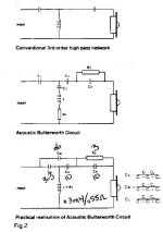
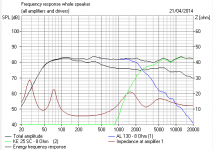
It's KEF's Acoustic Butterworth implementation of the Fs notch really.
It looks very good on paper, but the fly in the ointment is that it lets in a lot of subsonics which spoil the distortion performance.
It gets a very smooth 3rd order/18dB per octave rolloff, but it sounds horrible. The actual order of the filter is immaterial, it's just broken. Which is why it's sunk without trace. Fs notches in general are not as good as people believe. It's the subsonics that are the problem with them. 😛
This speaker needs a proper tweeter filter.
Attachments
Last edited:
Hi,
I see no evidence at all of a standard Fs notch and
quite frankly a large quantity of the proverbial.
Pontificating on Fs notches, you are not qualified.
rgds, sreten.
Here is a design that needs it :
Zaph|Audio - ZD5 - Scan Speak 15W8530K00 and Vifa XT25
My dear boy, It's built into the Visaton KE25SC!
I thought you would know that...🙄
Hi,
Being pathetic doesn't change you've said
nothing useful about the subject so far ...
Are you seriously suggesting the network
built into the tweeter should be removed,
or just talking b*ll*cks to try and make
out in some sense you know something
that quite patently you don't.
rgds, sreten.
So how do I measure this distortion you all are not agreeing about?
For now I don't even know how much there is.
Could also just be the room...
Sent from my iPhone using Tapatalk
For now I don't even know how much there is.
Could also just be the room...
Sent from my iPhone using Tapatalk
They are crossed at about 1,5kHz. The woofer is crossed using a 2nd order filter and the tweeter with a first order.
well, that is as wrong as can be
you have to use much steeper xo when crossing this low
but since you actually prefer it at loud SPL, I suspect you might have a phase problem
and could have been deliberately 'built in' to deal with the distorting tweeter
but also means it sounds muffled at low SPL
the 'ordinary' thing
but apart from that, nothing wrong with 'ordinary', if it works
So how do I measure this distortion you all are not agreeing about?
Hi,
You can try, but its pretty pointless, as the answer
will be too much. Common sense indicates a more
sensible x/o alignment, it is not more complicated.
rgds, sreten.
main problem is that you think your speaker is ok
makes you poke with the wrong end of the stick
so to speak
who designed this speaker ?
makes you poke with the wrong end of the stick
so to speak
who designed this speaker ?
I just Boxsimmed the Visaton BIJOU.
I knocked out the tweeter shunt to approximate the 1.5kHz crossover 2 way in all its horror. 😀
I also did a very rough sim of a third order at higher 2.5kHz crossover in Troels style, BBC slope and all. I expect it could be done better. 🙂
I knocked out the tweeter shunt to approximate the 1.5kHz crossover 2 way in all its horror. 😀
I also did a very rough sim of a third order at higher 2.5kHz crossover in Troels style, BBC slope and all. I expect it could be done better. 🙂
Attachments
 I've removed some rules-breaking posts. Behave, boys, or go involuntarily into read-only mode.
whether its been removed or not, the major problem with this tweeter could be its very high Fs
I don't know what the Fs (aka Resonance peak) of that tweeter is. It's notched anyway, though that doesn't help as much as you might think IMO. We are all guessing that it is just the combination of shallow slope and low crossover that causes the problem.
This is a long quote from our own Lynn Olson, but it's the key to the problem:
A common but unsuspected cause of sibilance is crossing the tweeter too low, or using a shallow-slope crossover. Many designers - unfortunately, a lot of them in the high-end biz - forget that direct-radiator drivers increase excursion at a rate of 12 dB/octave. Thus, it takes a 12 dB/octave highpass filter to merely keep excursion constant in the frequency range between nominal crossover and the Fs of the tweeter.
For example, if the tweeter has a typical Fs of 700 Hz, and the intended crossover is 2.8 kHz (again, typical), it takes a 12 dB/oct electroacoustical filter to merely keep excursion constant in the very critical 700 Hz ~ 2.8 kHz range. Part of the reason that this range is so critical is that audibility of distortion is at a maximum in the 1~5 kHz region. (Perception of distortion similar to, but not quite the same as, the Fletcher-Munson curve.)
Staying with the same example, if the electroacoustical filter is 1st-order (6 dB/octave), then excursion actually increases from 2.8 kHz on down, until 700 Hz is reached. Below 700 Hz, the excursion finally starts to decrease, but not very fast, only 6 dB/octave. This is troublesome because the maximum spectral energy of many recordings is around 300~500 Hz, so energy from this range can crossmodulate with the tweeter output.
This is why auditioning with little-girl-with-a-guitar program material and a full choral piece sound different. The LGWAG is spectrally sparse, and there isn't as much chance the tweeter will be struggling with IM distortion. Throw a dense, high-powered spectrum at the loudspeaker, though, and the tweeter will start to scream - and it is very audible on massed chorus as complete breakup.
At any rate, regardless of distortion of a particular tweeter (none of them are free of IM distortion), crossovers matter. Many designers want to take the tweeter as low as possible because the polar pattern is prettier and certainly measures nicer, but the inevitable price to be paid is more IM distortion resulting from increased excursion (the linear region is most tweeters is less than 1mm). Choosing a crossover is a difficult tradeoff between narrowing of the vertical polar pattern, IM distortion from out-of-band excursion, and how close the designer wants to approach the region of midbass driver breakup. The tradeoff is made more difficult when a rigid-cone (Kevlar, metal, ceramic, etc.) midbass driver is chosen, because the onset of breakup commonly falls in the 3~5 kHz region, right where the ear is most sensitive to distortion.
As you can see, the worst possible solution is a 1st-order crossover combined with a midbass driver that has a severe breakup region (Kevlar drivers, I'm looking at you). The 1st-order crossover fails to control out-of-band excursion, so program material in the 700 Hz-2.8 kHz region results in IM distortion in the tweeter's working range, while plenty of midbass breakup in the 3~5 kHz range gets through as well. And midbass breakup sounds the same as a bad tweeter, since the distortion and resonances fall in the same frequency range.
As a side note, most transistor amplifiers (including very expensive high-end products) go from Class A operation to Class AB around 1 watt. Feedback helps, but cannot fully overcome the two-to-one shift in transconductace as the AB region is traversed. In addition, thermal tracking is typically several seconds to a minute late (depending on the thermal mass of the heatsink and location of bias sensor), so the correct AB bias point is actually several seconds behind the program material. There are various sliding bias-tricks available (which avoid complete turnoff and associated switching transition), but they are all several seconds late. The more output transistors, the more AB transitions there are, since it is impossible to have transistors exactly match the switching transition - in production, they are matched for beta (current gain), but not usually for other parameters. Change the die temperature a bit, and the careful hand-matching goes away.
To recap, if you want lots of sibilance, use a midbass driver with severe breakup in the 3~5 kHz region (this is usually obvious from unsmoothed FR curves), pick a tweeter with limited excursion capability (not always spec'ed), select a 1st-order crossover at a low crossover frequency, and use an amplifier with a very large heatsink, many transistors, and somewhat unstable Class AB biasing (thermal overshoot). That should do the trick. Plenty of distortion from many different sources, even though the overall FR curves may look harmless.
Just to encourage tued, here's SEAS L15 metal cone plus SEAS 22TAF/G tweeter done right by Joachim Gerhard, the lovely Canalis Anima on third order acoustic crossovers:
An externally hosted image should be here but it was not working when we last tested it.
For all that, this combination is very difficult, IMO. Very hard to get flat.
Tued,So how do I measure this distortion you all are not agreeing about?
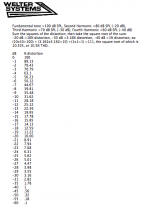
You can input a single frequency sine wave, then look at the output on a RTA (real time analyzer), the fundamental should be the loudest, the harmonics will show up as spikes above the fundamental frequency. The higher the amplitude of the spikes, the higher the distortion.
Although the tweeter is rated for "80 watts", try about a watt (2.83 volts) to start. You may find the distortion over 100% even with that level in the 1000-1500 range.
Art
Attachments
Last edited:
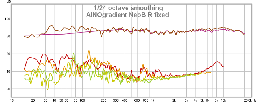
Tued, I use mostly RoomEQWizard (freeware) and minidsp UMIK-1 calibrated measuring microphone. REW is very easy and with good Help phrases, tutorials are numerous and even Youtube-shows can be found. You must register to hometheatershack.com to download it.
Holmimpulse and ARTA are not so easy to use.
A sine sweep is played, the program creates impulse response data and calculates several Graphics, also distortion at various frequencies. Then just adjust volume an see what happens.
Holmimpulse and ARTA are not so easy to use.
A sine sweep is played, the program creates impulse response data and calculates several Graphics, also distortion at various frequencies. Then just adjust volume an see what happens.
I'm using REW and getting some readings. The FR is what it is and it changing a lot. As I'm doing this in room...
Not much to do about that right now.
I'll take a deeper look into the many features of REW.
Not much to do about that right now.
I'll take a deeper look into the many features of REW.
I have a corrections to make.
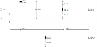
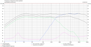
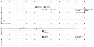
The filter on the bass/midrange is 4th order and on the tweeter we have a 2nd order. Sorry about that!
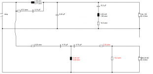
I'll most likely go ahead and try out a XO somewhat higher anyway.
Then I at least tried it out 🙂
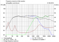
Here's the filter and the simulated response.
Will post an in room response once I get a proper measurement and when I have figured out to measure the distortion.
The filter on the bass/midrange is 4th order and on the tweeter we have a 2nd order. Sorry about that!
I'll most likely go ahead and try out a XO somewhat higher anyway.
Then I at least tried it out 🙂
Here's the filter and the simulated response.
Will post an in room response once I get a proper measurement and when I have figured out to measure the distortion.
Attachments
I'm using REW and getting some readings. The FR is what it is and it changing a lot. As I'm doing this in room...
Not much to do about that right now.
I'll take a deeper look into the many features of REW.
Sorry to say this, tued, but you are reinventing the wheel here. Which is to say you are wasting your time. 😀
Mr. Lynn Olson is not talking rot about low and shallow crossovers. Your "crispiness" is actually a moderate amount of distortion to vocals. The same happens with 8" bass units around 3kHz. The distortion happens to sound quite pleasant, having a sore throat or husky sort of sound. But it's still distortion, and it's going to sound quite nasty with complex pieces.
Most folks would choose 3rd (18dB/octave) or 4th order (24dB/octave) acoustic. They are lower distortion. Crossover point is the compromise between tweeter distortion and bass breakup.
Ah, wait. You are redesigning. Good.
Attachments
- Status
- Not open for further replies.
- Home
- Loudspeakers
- Multi-Way
- Why are my two-way visaton more crispy at high volume?