I notice a lot of the power amp use both NPN and PNP differential pair in parallel at the input. Most of the IC opamp use only either NPN or PNP differential input, not both in parallel. I understand with complementry differential pair input, you drive the top and bottom half of the power stage separately, but using a constant current source works just find for one half as in a lot of the opamp. Power amps a very much like the internal circuit of an IC opamp. Distortion depends on the open loop gain and the higher the open loop gain, the lower the distortion. Opamp does have very low distortion when closing the loop. What is the difference?
I don't know enough about distortion spectrum. I can't comment.
But when it comes to slew rate, you increase slew rate by increasing current. You must have a minimum slew rate target you want to hit, beyond that, it should not make any difference. Say as long as you can have enough slew rate to reproduce full power sine wave of 20KHz, it doesn't matter if one side can support 40KHz and the other side only support 20KHz.
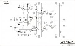
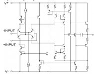
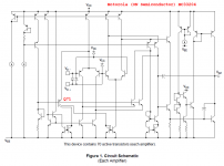
I just copy a typical schematic from another post here, it is simpler with only one differential pair. The top half is only a current source. Notice only one cap C9 and C10 in the signal path.
The reason I ask this is because using complementary differential pair doubles the amount of circuit, layout becomes more critical as parasitic can cause oscillation and likely you have to add caps to roll off the open loop gain at high frequency. That defeats the advantage of driving in both direction. I just traced out my Acurus amp today that has complementary input. The circuit spread out quite big, it's is like asking for trouble. I can see they use two caps to create two poles in the signal path. That is usually not good. Because the safest way is to have one dominant pole for stability.
I am not trying to be difficult, I am just curious.
But when it comes to slew rate, you increase slew rate by increasing current. You must have a minimum slew rate target you want to hit, beyond that, it should not make any difference. Say as long as you can have enough slew rate to reproduce full power sine wave of 20KHz, it doesn't matter if one side can support 40KHz and the other side only support 20KHz.
I just copy a typical schematic from another post here, it is simpler with only one differential pair. The top half is only a current source. Notice only one cap C9 and C10 in the signal path.
The reason I ask this is because using complementary differential pair doubles the amount of circuit, layout becomes more critical as parasitic can cause oscillation and likely you have to add caps to roll off the open loop gain at high frequency. That defeats the advantage of driving in both direction. I just traced out my Acurus amp today that has complementary input. The circuit spread out quite big, it's is like asking for trouble. I can see they use two caps to create two poles in the signal path. That is usually not good. Because the safest way is to have one dominant pole for stability.
I am not trying to be difficult, I am just curious.
Attachments
Last edited:
symmetry is eye candy
complementary symmetry looks good on the page even if the circuit doesn't work to expectation because you really already get the all the good of distortion compensation in the single polarity diff pair with good matching Q of the same type
there's no real circuit performance advantage to adding the complementary input pair with real parts
Last edited:
I think sometimes less is more. In IC, you can pack things very close. In discrete circuit, when you have long trace, noise and parasitic can really come into play.
Do you know of any site to download schematics of Krell power amp. I have been on google for a few times, it is hard to find their schematic.
Do you know of any site to download schematics of Krell power amp. I have been on google for a few times, it is hard to find their schematic.
No one has commented that the early IC fabrication processes could not produce decent complementary transistors so the IC people didn't have much choice. They came up with a pretty effective circuit that became more or less standard.
In a discrete power amp you have the choice, complementary input does have the potential benefit of lower noise, and the input bias current cancellation may allow you to simplify, perhaps eliminate a DC servo or an electrolytic in the FB network.
If you do want a push/pull VAS then a complementary IPS is similar complexity to a one sided version with the extra circuitry to convert to push/pull.
But perhaps not worth the effort unless you really want ultra-low noise or distortion.
Best wishes
David
Last edited:
The dearth of complementary designs in ICs may have more to do with the expense of a fabrication process that can make decent vertical PNPs on the same chip as NPNs. It's a lot more process steps.
{edit: oops Dave Z you beat me to it}
But as Abraxalito implies, there is almost no need for complementary designs.
Regarding the disto spectrum, I think a complementary design will in theory cancel out even-order harmonic distortion, leaving only odd-order harmonics. So maybe it theoretically cuts thd in half at the expense of all that complexity, which might have been better used for more intrinsic linearity in one half of the circuit. Also, even harmonic disto sounds "better" than odd, right?
Last edited:
N
In a discrete power amp you have the choice, complementary input does have the potential benefit of lower noise, and the input bias current cancellation may allow you to simplify, perhaps eliminate a DC servo or an electrolytic in the FB network.
David
But this is power amp, noise should not be an issue, particular it's so easy to find a low noise transistor now a days. The input impedance is usually less than 50K, bias current should not be an issue.
The dearth of complementary designs in ICs may have more to do with the expense of a fabrication process that can make decent vertical PNPs on the same chip as NPNs. It's a lot more process steps.
I know what you mean, I design analog IC before. Back in the 80s, we mostly use lateral PNP in the IC. But surprisingly ,quite a few of the old opamp use PNP as the input differential stage. I always question why.
Less 1/f noise, apparently (i.e. higher beta). And it means you've got an npn VAS. Input transistors tend to be fast enough anyway.
I'm a bit surprised that there haven't been more votes in favour of the complementary differential input. It has some nice traits such as (partial) input bias current cancellation, which ought to reduce input impedance distortion at higher tail currents, and tends to perform well in practice.
I'm a bit surprised that there haven't been more votes in favour of the complementary differential input. It has some nice traits such as (partial) input bias current cancellation, which ought to reduce input impedance distortion at higher tail currents, and tends to perform well in practice.
But as I said, noise is not important for power amp and low input impedance make bias current irrelevant. I am actually surprised people don't just use an IC opamp as the first stage. Everything is superior with a real opamp.Less 1/f noise, apparently (i.e. higher beta). And it means you've got an npn VAS. Input transistors tend to be fast enough anyway.
I'm a bit surprised that there haven't been more votes in favour of the complementary differential input. It has some nice traits such as (partial) input bias current cancellation, which ought to reduce input impedance distortion at higher tail currents, and tends to perform well in practice.
Last edited:
People don't like to stray too far from the Lin topology. Op amp input stages usually mean doing something else. CFP-with-gain output stages, flying rail topologies, or extremely high feedback (op amp plus conventional VAS) all have quirks that make designers nervous.
All of my PA and most of my Hi-fi amps use op amp plus conventional VAS topology. Once I learned how to stabilize it, it became the obvious choice. All that feedback gives the bass SLAM needed for PA (if the power supply is up to the challenge), using the right op amp makes it immune to any conceivable input overload, and I never have to match input pairs or set the DC offset.
All of my PA and most of my Hi-fi amps use op amp plus conventional VAS topology. Once I learned how to stabilize it, it became the obvious choice. All that feedback gives the bass SLAM needed for PA (if the power supply is up to the challenge), using the right op amp makes it immune to any conceivable input overload, and I never have to match input pairs or set the DC offset.
The complementary differential input stage has been used for more than 45 years, and is still going strong in higher quality audio designs.
It has a number of advantages that have not been noted here.
Its main advantage is that it easily provides a push pull drive to the VAS or the second stage that has to work harder than any other stage in the amp, as it has to swing the entire +/- voltage range and still give significant voltage gain.
However, it just so happens that symmetrical topologies tend to cancel even order distortion, AND provide complementary loads for each stage, and this eliminates the passive load, often necessary in order to provide DC current to the second stage. Removing this 'bias' or load resistor, allows for less current change in the stage when creating the necessary output voltage to drive the output stage.
This topology is sometimes used in IC's but it is difficult to do because it requires truly matched npn and pnp devices, and these only became available in recent years. However Harris made one decades ago for example, using dielectric isolation technology. Because it was an expensive process, IC designers were forced to stick to single differential input designs which has done about as well as the complementary differential for just op amps. However, with discrete solid state design, complementary differential offers real advantages over a single differential input stage.
just search this Forum.I think sometimes less is more. In IC, you can pack things very close. In discrete circuit, when you have long trace, noise and parasitic can really come into play.
Do you know of any site to download schematics of Krell power amp. I have been on google for a few times, it is hard to find their schematic.
There are many Krell threads and many of the schematics are posted here.
For another take, just read the Leach paper "Lo Tim"
observations...
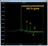
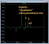
(below 1) - A typical (better) "Leach" type symmetrical input stage.
Examples : H/K990 or professor Leach's project ...
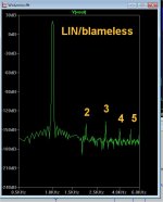
(below 2) - A typical LIN (blameless).
Examples: most of the forum projects .... "Badger/wolverine" or any
other D.Self inspired circuit. PS - had to use more input - this
amp's distortion was below the noise floor ! BUT , it does not totally cancel out
the 4th harmonic , even with it's super low THD (a drawback ?)
(below 3) - The "hybrid" , when you use a LIN input pair plus either
a symmetrical intermediate stage (Ampliwire) OR a level -shifted
symmetrical voltage stage only (less parts).
I often wondered what was "up" with the Electrocompaniet" "style" ??
All those extra parts... (a whole 2nd input stage !) .
Tried to standardize all factors (with the exception of 2 below),
70ma bias Class A 3w triple output stage ....
Most amp simulations follow these rules of cancellation vs. topology.
The latest CFA projects on the forum are like the "Leach", as well.
Also , a symmetrical IP stage will usually have a faster slew rate +
better overload characteristics.
OS
(below 1) - A typical (better) "Leach" type symmetrical input stage.
Examples : H/K990 or professor Leach's project ...
(below 2) - A typical LIN (blameless).
Examples: most of the forum projects .... "Badger/wolverine" or any
other D.Self inspired circuit. PS - had to use more input - this
amp's distortion was below the noise floor ! BUT , it does not totally cancel out
the 4th harmonic , even with it's super low THD (a drawback ?)
(below 3) - The "hybrid" , when you use a LIN input pair plus either
a symmetrical intermediate stage (Ampliwire) OR a level -shifted
symmetrical voltage stage only (less parts).
I often wondered what was "up" with the Electrocompaniet" "style" ??
All those extra parts... (a whole 2nd input stage !) .
Tried to standardize all factors (with the exception of 2 below),
70ma bias Class A 3w triple output stage ....
Most amp simulations follow these rules of cancellation vs. topology.
The latest CFA projects on the forum are like the "Leach", as well.
Also , a symmetrical IP stage will usually have a faster slew rate +
better overload characteristics.
Doug self says they do not ... But , I do not agree.complementary differential offers real advantages over a single differential input stage.
OS
Attachments
Last edited:
The problem with blameless is :why would you intentionally design a front end stage where the drive and slew rates were not symmetrical? Even order distortion cancellation another benefit.
Single ended IPS driving a P-P solves some of these objections, but the bal IPS is still the most elegant.
As to all the commentary about problems with balanced complementary inputs in books etc, I'll let the numbers do the talking . . .
Single ended IPS driving a P-P solves some of these objections, but the bal IPS is still the most elegant.
As to all the commentary about problems with balanced complementary inputs in books etc, I'll let the numbers do the talking . . .
Last edited:
But this is power amp, noise should not be an issue,...
Not for most applications.
But my personal system, for instance, has horn compression drivers and I drive them directly, bi-amped.
So I have a sensitivity of about 115dB 1 W @ 1m rather than passive crossover of perhaps 90 db, often less.
That makes noise an issue. Headroom, on the other hand, not so much😉
Best wishes
David
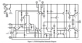
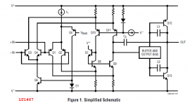
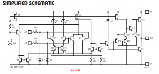
Let me show you four more of them. You will enjoy deciphering the function and purpose of Q71 / Q5 / Q5 / Q4 .Incidentally here's the only complementary IC I've come across - NJM2136
These opamps have similar internal guts because they are designed for similar external specifications, which you can peruse on mfr websites if you like.
Attachments
- Status
- Not open for further replies.
- Home
- Amplifiers
- Solid State
- Why a lot of power amps use complementry differential input?