Hi Pieter T!
Tyimo
What is the thickness of this GOSS lamination? 0.11mm?Alpha c-cores come in M4-011 grain oriented silicon steel, which is already better for audio transformers than M6-014.
Tyimo
Last edited:
Hi Pieter T!
What is the thickness of this GOSS lamination? 0.11mm?
Tyimo
No.
011 is number of mils (thousands of an inch); 011 is 0,28 mm.
M6 is normally 0,35 mm.
Thanks!
Do you know where can I buy in Europe even thinner laminations in normal GOSS?
I am not sure at the moment.
Waasner in Germany do c-cores but I am not sure if they have the thinner laminations, and they have become pretty expensive over the last years.
In your own country there is a company called Fastron, which is allied to a German company with the same name (joint venture); I don't think they do thinner laminations.
I might be able to help you when you indicate what you need.
Anyone using a DIY winding machine? I'm planning on building one soon so i can start practicing
http://www.dissident-audio.com/AutoIndex/index.php?dir=Pst/&file=Bobineuse.zip
I would like to buy something under 0.2mm or 0.1mm thickness, but not amorphous or nanocrystalline or anykind of special and very expensive material.I might be able to help you when you indicate what you need.
I made already an OPT with amorphous 0.022mm C-core and it has fantastic sound. Now I would like to test something similar with GOSS.
Tyimo
Rvrazvan, Just how elaborate do you plan on making the winding machine. If it is for a couple of one off items you can use an electric drill, mechanical counter, and somes spring for pretension.
If you go to the German website link I posted a few pages back you can see a really nice DIY winding machine. Christl has a longitudinal screw to automatically advance the winding per the wire gauge, digital readout for turns and varying speeds and tensions. He has all of the plans on the site.
Christlludwig.com in German.
I hope to have something crudely assembled by this weekend so as to begin this winding journey. I am going to do the dual C-core like Mac does. It is also easier to band together.
And all thanks again for the Alpha C-core website. Truly a bargain on cores.The guy on Ebay wants 75.00 for a core Alpha sells for 11.00.
There is also a nice bit of additional information available on the parent company Bridgeport Magnetics main site. They have a decent price on toroids and custom transformers. The toroids are in line with what Antek charges for stock ranges.
Now if all of this goes as planned how do you test and measure the spec's for the DIY output transformer. I am fairly confident they will work but do not know how well.
Also, on the Christl website he uses 230 volts on the power supply tranny. How exactly would I redo that for 120 volt primary input. I am thinking larger wire with half the turns.
Tad
on the Christl website he uses 230 volts on the power supply tranny. How exactly would I redo that for 120 volt primary input. I am thinking larger wire with half the turns.
half the turns is okey, about 3 wire sizes up should do, if the 230v wire size is a gage #24, then the 117volt wire size can be a size #21, of course you still have to find out if you have space, if you have more you can still go for a size bigger say #20.....you can consult wire tables, American wire gauge - Wikipedia, the free encyclopedia Copper wire Wire Gauges
Wow. The german guy is really :showing of" with that winding machine 😀
I want a simple design. just variable motor and and a counter. i will have a large gap between the wire tensioner and the bobbin so that the wire will advance by itself. i dont't know how this will work with very thin wire but with with a larger diameter it will work just fine. I want a semi-automatic machine for now.
Thank you for the links guys.
About alpha cores. Maybe we can organize a group buy for europe thus reducing the costs of transportation.
<snip> Just look at John Curl's Blowtorch preamp. It is a mess of spiderweb wiring and yet costs what a small house does. Go figure.
<snip> Tad
It is??
Really?
Actually there is not that much wiring in it at all... and yes it is not bundled into "mil spec" laced harnesses for good reason...
_-_-bear
Some time ago I had a MC275 on loan; a good amp but actually, and a bit to my disappointment, nothing "special", not quite what I expected as I was especially interested in the unity coupling design.
At the same time I dismantled a shorted MC275 output transformer and so I was able to check winding ratios. It became clear that the MC275 is a design applying all "tools" to get the most power out of a pair of KT88's: cathode feedback in the output stage, therefore requiring additional gNFB. Huge voltage gain in input and driver stages because the power stage has little gain. Lowish primary impedance of the output transformer, a.s.o. Result IMHO is an amp with power and decent specs but not a champion in refinement; I'd say for a tube amp it is a real power horse.
When you want to make something McIntosh like, try to improve on the design; it is not that difficult.
I indicated before, but take a look at Hugh Alvin Lockhart's design of the same principle, designed at about the same time, improving on some important things, especially primary impedance of OPT and an elegant driver stage (6SN7 - interstage transformer) which gives the required voltage swing without all the MC275 tricks. When you succesfully wind the opt's, the interstage transformers are a "gimme". Lockhart even shows winding schemes (using c-cores, yess!!).
The stock McIntosh amp using carbon film resistors, old school anemic power supply filtering and yesterday's caps? That one? 😀
Don't condemn the basic design on the basis of an implementation?
The original McIntosh 50W-2 uses an interstage transformer. Fyi.
And, no interstage transformers are not a "gimme" at all. Go ahead and show me the commercially available interstage that really does work well. Show me one that really permits the wide bandwidth that the typical McIntosh amp is able to acheive? Not so easy, not so simple. One of the problems is that the grid of a tube that runs into AB2 is not such a nice simple load.
The Lockhart design is interesting, but from a non DIY point of view the commercial product that this design represents would be substantially more expensive to produce. Then the question is "does it really provide a significantly better result?" The answer is simply, not likely from a business and marketing point of view.
To answer the question asked about why winders don't "spill the beans" on their techniques and tricks it is because there is a lot of trial and error in terms of the practical implementation as well as subtleties in all sorts of areas in terms of getting a good result and an effective winding pattern, which means a design that works for production - even small runs by a small shop. Even something as simple as "bring the wires out here, not there..." might be the result of a whole lot of time invested.
_-_-bear
Bear,
I was in know way condemning John's Blowtorch preamp. The main substance was to show that there are individuals of sorts with humongous financial resources that create a small niche market for exotic one off items. The audio tube market is just one such arena. The other being woman's shoes and purses.
In the Lockhart link for the Mcintosh 50 watt amp it seems from the white paper that this amp never did reach a full 50 watt output. Something bordering on 37 watts with 3 percent distortion. Not bad for a quick to the patent office prototype. I really wish I could get my brain around exactly what is going on in the unity coupled circuit. Maybe with a few more years tinkering at this it will start to bear fruit.
I am just getting the stuff together for my weekend winding project. It so happens a guy at work had on of those old push type counters in his drawer. I can rig up some sort of flipper to advance the counter on each revolution. The price was sure good. I always like free.
Now to get something to hold the bobbin so it will be easy to remove with all of the wire tension on it. And a suitable medium to construct the bobbins out of.
Tad
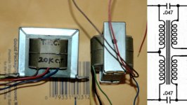
Seems that making transformers now is a real project. More time spent finding what I used to get for FREE! Also if there is any old stuff out there, no way to find it. All of the electronic recyclers are gone. They were everywhere in the 70s and 80s. And nothing has transformers anymore but the high frequency ferrite things. Winding the driver transformers is a real project. Extremely fine wire. I used # 38. I didn't try Bifilar because you need triple, or quad insulated magnet wire and that is special order. Double called heavy may work, but tests I made showed it easily shorted when a little over 400 volts was applied. The first thing I tried was interleaved, but this had very poor response with a lot of hills and valleys. Second was 4 coils side by side. This worked great. The last ones shown here are one coil over the other with one wound in opposite direction. Input and output go to the center part where coils meet. Both of these designs need a 0.047 to 0.1 Uf cap from input to output. Each winding is about two thirds regular wind, and the last part on signal end is scramble wound.
Attachments
And, no interstage transformers are not a "gimme" at all. Go ahead and show me the commercially available interstage that really does work well. Show me one that really permits the wide bandwidth that the typical McIntosh amp is able to acheive? Not so easy, not so simple. One of the problems is that the grid of a tube that runs into AB2 is not such a nice simple load.
Please see it in the right perspective; compared with the more or less complex output transformers the interstage transformers are not. If you could live with some 150kHz with for instance an ECC99 driver tube you could try me....
Driving a tube which runs into AB2 is exactly where interstage transformers excel! "Not such a simple load" - grid current: the low DCR secondary of the interstage transformer is much better here than a highish fixed input resistor.
The Lockhart design is interesting, but from a non DIY point of view the commercial product that this design represents would be substantially more expensive to produce. Then the question is "does it really provide a significantly better result?" The answer is simply, not likely from a business and marketing point of view.
When I am right this is a DIY forum....
And, no interstage transformers are not a "gimme" at all. Go ahead and show me the commercially available interstage that really does work well. Show me one that really permits the wide bandwidth that the typical McIntosh amp is able to achieve? Not so easy, not so simple. One of the problems is that the grid of a tube that runs into AB2 is not such a nice simple load.
Hands down the hardest transformer to design in audio. The balance between capacitive coupling, capacitive loss and amount of inductance required, eliminates any sort of universal design. The worst are push pull to push pull and the easiest are single ended to push pull. The tiniest sort of changes can cause a minus 6 db at 12kHz to change to a plus 6 db at 35kHz.
Bud
Please see it in the right perspective; compared with the more or less complex output transformers the interstage transformers are not. If you could live with some 150kHz with for instance an ECC99 driver tube you could try me....
Driving a tube which runs into AB2 is exactly where interstage transformers excel! "Not such a simple load" - grid current: the low DCR secondary of the interstage transformer is much better here than a highish fixed input resistor.
When I am right this is a DIY forum....
I think this is what you intended to post...
If you have a low DCR secondary, it sounds like you have a step down interstage?? dunno what you have found, I've found that the interstage is a difficult beastie, size is not the issue, they are just as complicated to wind as is an output.
Btw, I'm not comparing it to a "fixed resistor".
I am unaware of interstage xfmrs off-the-shelf that will get anywhere near 150kHz., but they may be lurking out there... afaik ANY xfmr that makes it out to 150kHz is very rare.
If you can tell me/us of any, I'm interested! 😀
_-_-bear
Hi Pieter T!
Greets:
Tyimo
Have you got any info about where to get GOSS laminations under 0.2mm thickness?I might be able to help you when you indicate what you need.
Greets:
Tyimo
I think this is what you intended to post...
If you have a low DCR secondary, it sounds like you have a step down interstage?? dunno what you have found, I've found that the interstage is a difficult beastie, size is not the issue, they are just as complicated to wind as is an output.
Btw, I'm not comparing it to a "fixed resistor".
I am unaware of interstage xfmrs off-the-shelf that will get anywhere near 150kHz., but they may be lurking out there... afaik ANY xfmr that makes it out to 150kHz is very rare.
If you can tell me/us of any, I'm interested! 😀
_-_-bear
No step down; just 1:1.
The comparison with the "fixed resistor" is because the interstage secondary replaces the 50k, 100k or whatever input resistor of the next (mostly power) stage. The secondary DCR can be some some 200, 400 or 600 ohms, and that is why it is working that well with grid current situations for tubes switching from A1 to A2.
- Status
- Not open for further replies.
- Home
- Amplifiers
- Tubes / Valves
- Who makes their own OPT around here?